woody said:You could try a biased bipolar for C1. 2 pair of 10,000uf 50v caps in seriese ( + -- + ) so you get a 100v 10,000uf bipolar cap then connect the center - terminal to ~ -20v through a high resistance. I have used a biased bipolar in another aplication where it realy made a big difference.
I do plan to test this solution. But, speaking about my current solution, I would like to mention that really "transparent" sound from Zen9 was achieved by paralleling 30 pcs of 680 microF "good" elecrtolytic capacitors. What means "good" ? I did measurements of impedance Z of various electrolytics at 10 kHz. Impedance value consist of its module and the Fi angle. Ideal capacitor would show Fi = -90deg at all frequencies. But, most of electrolytics give Fi in the range from -0 to -30 degrees at 10 kHz. The 680 microF capacitors that I used shown values close to -60deg at 10 kHz, and they really improved the sound. I do not name them, since any manufacturer could have similar low-ESR capacitors, and they can be quite cheap. 30 microF shunting polypropylene capacitor also used.
This finding will work also for power supply electrolitics in Push-Pull schematics.
Last edited:
Some new experiments with various preamps connected to the Zen9-50W have revealed large sound sensitivity to properties of the preamps. The best sound (authoritative and detailed at the same time) was obtained with SIT-transistor based preamp. It is discussed in the thread called "Crazy" power for preamp". This thread was started in the Upgrade Island and will be imported to permanent forum, as promised, within few days.
VladimirK,
Your work is so remarkable. I want to do the same experiment. But need to confirm the final circuit. could you share the 50W version?
I have replaced IRF240 by 3 x 2SK1058, total current 3,8A, all electrolytics replaced by Elna Cerafine + MKP, output capacitor as I described before (even 100 uF Solen MKP shunt now). Power supply 2 x 150000 uF. Bass is very OK with Paradigm Studio 100 v4. Highs are as in my dreams. Waiting for arrival of new loudspeakers PMC EB1i.
Have you considered to try out the Semisouth JFET's ?
To me they seem like the ticket for this type of amp.
Magura")
My vision is that capacitors and proper assembling are more important. Now I feel limitation only from speakers. I guess we still far away from the best of Zen9 possibilities. I really grateful to Nelson for this simple and ingenious schematics. Increasing power we almost do not create difficulties with nonlinear Ciss of output stage transistors.
I have replaced IRF240 by 3 x 2SK1058, total current 3,8A, all electrolytics replaced by Elna Cerafine + MKP, output capacitor as I described before (even 100 uF Solen MKP shunt now). Power supply 2 x 150000 uF. Bass is very OK with Paradigm Studio 100 v4. Highs are as in my dreams. Waiting for arrival of new loudspeakers PMC EB1i.
If Paradigm with Zen9/50W can do great highs and very ok lows. That is a good sign that JFET power amp. could be a great new design model for more wider prospects of speakers. Not only full range.
one more questions, besides put more current, the voltage should be higher, right? So power trans voltage output should change from 18+18V to ??
(sorry I am relatively new to SS amp DIY, I was a tube amp DIYer before)
Thanks,
Yes, I use two separate external power supplies with 800VA trafos each, 48V secondary, approx +60V rail voltage under 3,8A load. Connection of power supply with main block is made by cable on the basis of Analysis-Plus speaker cable, connectors are original Neutrik Speakon. Rectifier uses Shottky diodes (100V and from 30A to 50A would be OK). 50000uF inside each power supply and 2x90000uF in the main block. Every electrolytic capacitor is shunted by polypropylene or polistyrene (near 0,1uF). Connection point to the capacitors rails should be chosen by measuring impedance in various possible connection points.
VladimirK;1979275 Every electrolytic capacitor is shunted by polypropylene or polistyrene (near 0 said:A lot of key points.
Only don't understand clearly the last part as quoted.
So you mean we shunt every electrolytic (50000uf & 90000uF)by one 0,1uF cap? And we use a rail to connect the PSU capacitors then choose the right connection point of that rail to the secondary winding and earth, choose the lowest impedance point. Do I understand right?
Thanks,
A lot of key points.
Only don't understand clearly the last part as quoted.
So you mean we shunt every electrolytic (50000uf & 90000uF)by one 0,1uF cap? And we use a rail to connect the PSU capacitors then choose the right connection point of that rail to the secondary winding and earth, choose the lowest impedance point. Do I understand right?
Thanks,
Every 10000uF single capacitor (14 pcs of them at PSU per channel) is shunted just to suppress locally undesirable HF and decrease rail impedance and dielectric losses at 20kHz. Since the whole construction of 14 caps is big enough, one must consider question where to connect wires from diode bridge and to amp schematics. Testing various connection points one may observe variation of impedance and dielectric losses.
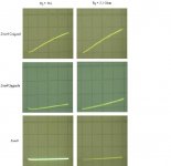
Just for testing low frequency features of Zen4 and Zen9 I measured square wave responce (10Hz, 30V peak-to-peak) at various resistive loads. Also the Pioneer A-66X amp was measured. The negative parts of square wave are shown in the picture. With 2.05 Ohm load the output current is close to 6 Amps. It seems that both Zen4 and Pioneer have some problems with the values of interstage coupling capacitors, they can not keep on square signal even without load.
Attachments
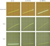
I have managed to add 50 uF film capacitor to C2 (Zen4 schematics). Now square wave looks better, but general impression from Zen9 sound is better still. Upgraded Zen9 sounds as a big amp without any reservation, while with Zen4 one should justify it by its belonging to FirstWatt league.
Attachments
Last edited:
So what all output power ZV9 on classical scheme and 46V supply?
Zen9 is probably a most suitable schematics for easy power upgrade. With 48V AC transformer secondary voltage I have nearly 60V power supply output voltage at 3,8 A bias current. Output power can be calculated from: 54V peak-to-peak voltage and 7,6A maximum current. Everything important for making the upgrade has been wrote by Nelson in his Zen articles. To make first step from the original Zen9, just use more transformer power, larger number of capacitors in PS filter, shottky diodes rectifier, good output electrolytic capacitors, bigger film shunting capacitors, and use also film shunt with the Aleph current source capacitor. Outcome will be essential. Sound is very clear, situation with no traces of capacitors artefacts can be achieved, and on the top of this it is a sweet single-ended schematics.
Last edited:
Several months ago I have got new speakers - PMC EB1i, also I have three amps -
1) tube 300B SE from Eraudio (60kg weight, Zout=0,6 Ohms)
2) Zen9 with LD1010 - 3x2SK1058 - 3x2SK1058 3,8A Zout=0,8 Ohms
3) Zen9 monoblocks with LD1010 - 3x2SK1529 - 3x2SK1529 4,8A Zout=0,4 Ohms
and a preamp with 22dB amplification based on SIT transistors KP926A.
The amp 1) acts as a reference for the mids and highs reproduction.
The speakers do not have impedance deeps, impedance is very flat from 50Hz till 500Hz in the region 3,8...4,2 Ohms.
I have tested very simple way of achieving good bass reproduction. In Zen9, just changed resistors of NFB divider to 3k4 and 6k8, also adjusted NFB compensation cap to 30...60pF. Zout now are 0,34 and 0,15 Ohms, it is comparable with speaker cables resistance. Power supplies are external, 2x1kW trafos.
Bass now almost perfect. Very tight and powerful in 6x5,5x3m room. As for highs, they are the same, or very little worse, almost impossible to distinguish.
Last edited:
Dear VladimirK,
have you ever managed to measure capacitancies of КП926А or shall I say ПК-15? What resistance has the device you've used? The ones I have are in the range of 1 to 100 Ohms.
Discussing this will be off-topic for the current thread. Gate capacitance of KP926A is not small, close to 1500pF. In the preamp mentioned above I used KP903A with 12pF gate capacitance, cascoded by KP926A. Load is also KP926A.
I have measured Id vs Uds curves at various negative Ugs, they are triode-like and show internal resistance d(Uds)/d(Id) near 100 Ohms.
Last edited:
- Status
- This old topic is closed. If you want to reopen this topic, contact a moderator using the "Report Post" button.
- Home
- Amplifiers
- Pass Labs
- The 50W version of Zen9