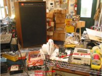
Well, I connected the 10AWG ground wire to a barrier strip on the bench so I have a single point ground reference. Then I set up isolation transformers for the computer and monitor since the computer is the most likely source of noise. I can see it on the sound card output even though in loop back it looks clean.
It made a slight improvement.
Now that I have the bench cleaned off I'll wire both inputs of the sound card so I can use one for the ground reference input.
Next order to Edcor I'll get a couple of isolation transformers to play with. Thanks dsavitsk.
Latest plot shows lower distortion and higher s/n so I'm moving in the right direction.
Which brings me to the question of what standard to test to?
what weighting? "C weighted"? I turned it on.
What cut off frequency for the lower cutoff ? I've been using the default 200Hz.
Is there any standard for comparison purposes or is it just a matter of 'whatever floats your boat'?
Do you see noise on the soundcard output when it's looped back to the soundcard input? If not, your noise is coming from another source.
I have not looked at the signal with the 'O' scope, but the plot does not show the noise if the soundcard output is looped back to the sound card input and the shield is left floating on the terminated end. However, if I connect the shield to reference ground I did see noise.
It seems to me that this indicates that there is (1) a ground loop causing noise pick up, or (2) Noise generated by the computer is flowing through the grounded shield and inducing noise into the signal.
What other possibilities exist?
Would this be a better coupling transformer? Although it would have more limited use I suppose.
EDCOR - WSM10K/10K
Last edited:
I've been using the default Rife-Vince3 with 256K points and averaging 3 transforms. This takes about 15 seconds. I could drop to 64K points and get 1Hz resolution then increase the number for averaging to keep from taking too long.
Other window options include Rife-Vince1 and 2, Blackman, Blackman/Harris, Flattop, Van Hann, and Hamming.
Other window options include Rife-Vince1 and 2, Blackman, Blackman/Harris, Flattop, Van Hann, and Hamming.
Do not succumb to the temptation to float the PC, the PSU in many PCs has appreciable leakage current and you could create a minor or not so minor hazard.
This point can not be emphasized enough. I went to great pains to use HCNR-201 analog optical isolators for my tube tracer -- after hearing from a friend who had fried a mother board.
I was going to try an old radio shack 600:600 ohm transformer to convert single end to diff and run that, but I think I threw it out. RS does not carry them locally although they are listed on the web. It would have been a cheap test up to around 5KHz.
If you want very high quality 600 ohm transformers, consider getting a HP 353 Patch Panel on Flea'bay -- folks would just throw these out and keep the oscillator and true-rms meter which came with the telcom test kit. The patch panel can be very useful. The manual isn't on BAMA, but I have a PDF somewhere.
Here's an FFT of another Adcom 565 I am working on -- it was averaged 64X. The cables are decent quality 50 ohm RG-58/U
An externally hosted image should be here but it was not working when we last tested it.
I have not looked at the signal with the 'O' scope, but the plot does not show the noise if the soundcard output is looped back to the sound card input and the shield is left floating on the terminated end. However, if I connect the shield to reference ground I did see noise.
It seems to me that this indicates that there is (1) a ground loop causing noise pick up, or (2) Noise generated by the computer is flowing through the grounded shield and inducing noise into the signal.
What other possibilities exist?
Would this be a better coupling transformer? Although it would have more limited use I suppose.
EDCOR - WSM10K/10K
That's weird that you get the noise with only a loopback and only then when the shield is connected at both ends. It could be that your soundcard is picking up something from the computer it's plugged into.
It sounds like maybe an input transformer is a good thing to try next.
Edit: One other thing, you might try lifting the shields of your soundcard I/O at one end; for example leave them connected at the computer end (easier to do) and lift them from the end where they connect to your amp. You already have a ground connection from the computer to the bench star ground, right? Maybe your noise current loop is going through the ground on the souncard I/O.
I am amazed with my setup thet once I got the ground sorted out, it's now pretty much immune to having the flourescent lights on, my noisy inverters, etc...
Last edited:
...
Here's an FFT of another Adcom 565 I am working on -- it was averaged 64X. The cables are decent quality 50 ohm RG-58/U
Well there's another solution; get an AP box! The I/O is pretty good on those ;-)
Which AP is that one? I'm starting to get interested but am not sure what real performance to expect from each... I think I will need a 520/525 or a System 2 to get better than 100db measurement range...
-100dB down is beyond my working brain: I'm much noisier than that. However, even at -80down I found my bench was contributing to the hum; the old trick of slipping a sheet of ally between the mat and bench and grounding it to the chassis works wonders.
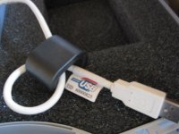
Also got a large sized ferrite ? a couple of turns of the USB cord also reduced unwanted spikes as did the mouse cable.
richy
Also got a large sized ferrite ? a couple of turns of the USB cord also reduced unwanted spikes as did the mouse cable.
richy
Attachments
I'll try the mouse and keyboard cables.
I put ferites on the audio in, out and both together with no effect.
I've considered putting copper sheet on the workbench. I think I have a piece of .032" that is 12" x 6' that I could make a ground plane out of.
Hmmm. I think you still have grounding issues to work out before building the 10x10x10 Faraday cage ;-) It's more likely going through a wire than the air.
Make sure there is exactly one conductive path from each piece of gear to your ground. I think there may be someting going on between your computer power supply and soundcard ground from your description. Try lifting the shields at one end...
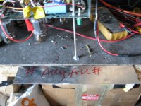
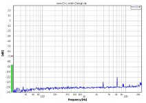
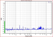
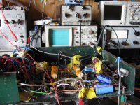
I have a noisy EMI environment and noisy power, and all I've done is make sure I have a single ground reference point in the system. 1st pic is my loopback with the generator muted, 2nd is the amp running on the bench with the generator muted. The test bench itself is a (grounded) wire rack with a melamine shelf board on top. Wiring from the generator to the amp includes a loosely twisted pair of 24" grabber leads.
Attachments
Last edited:
-100dB down is beyond my working brain: I'm much noisier than that. However, even at -80down I found my bench was contributing to the hum; the old trick of slipping a sheet of ally between the mat and bench and grounding it to the chassis works wonders.
Also got a large sized ferrite ? a couple of turns of the USB cord also reduced unwanted spikes as did the mouse cable.
richy
Good Point!
-100db from where? one volt (dbV)? one milliwatt into 600 ohms(dbm, dbu)?
My reference for power amp output is one watt (2.83VRMS into 8 ohms) so my -100 db corresponds to 28.3 microvolts if I did the arithmetic right.
Empirically, the hum audibility threshold with my speakers is a few millivolts (-60db ref 1W) at 120 Hz. At 1KHz, it's a few hundred microvolts (-80db ref 1W) This is for pure sine tones in a very quiet room at about a meter from one loudspeaker (JBL4312).
I don't think 20db from sine tone audibility to the measurement floor is excessive, but then I also need to test gear like mic preamps and A/D converters that have much wider specs for dynamic range.
Good Point!
-100db from where? one volt (dbV)? one milliwatt into 600 ohms(dbm, dbu)?
.
Yup 0.775V is my ref 0dBu. That lines up exactly on the scale on my HP332A. The rest is easily memorized. Somewhere there is a chart with all this stuff; mentioned some years ago but since vanished.
So those with digital fft analysers able to hit -100dB+ must have excellent effective number of bits in vertical resolution.
Looking at the photo, there are other benches looking like an element of havoc (mine) in this forum, Kein wunder the noise is up but it works ! Experience counts.
richy
Attachments
Maybe I'm reading this wrong as I don't have a good point of reference yet.
I've seen amps spec'd at 85dB s/n. I'm testing a single amp stage and getting around 72dB s/n so my intrepretation is that all the noise I see is degrading my s/n ratio. It is also obscuring my ability to see intermodulation noise such as the 60hz induced side lobes around the 1KHz main test signal.
While additional gain stages and output stages will increase the output level, they will also amplify the noise, hence the s/n will never get better, and will in fact degrade further.
I'll work on my ground again this weekend.
A design rule of thumb I have:
The old Mullard 20W 3 stage amp using EL34, ECC83 LTP, EF86 front end was capable of a -90dB/w noise figure. Okay it used 30dB global nfb, which accounts why it sounded sterile on "MI". It was hated on the stage.
It was a "thingy" of the mid 1960's, designers of tube amps had to compete with the new solid state on low noise levels. The challenge was on. The same time trains in the UK were fitted with aircraft seats to try and win over customers. Any method was used to convince.
The Williamson amp, a generation earlier, using a 0.9 gain concertina effectively required a medium gain diff driver and front end triode so this noise figure increased to around -75dB/w, quite a bit worse with only 20dB global nfb. If one tried to squeeze 30dB global nfb out of the available Williamson technology you'll end up with a howling protest.
With modern transformers one can design for 20dB global nfb with a 15dB stability overhead margin and still get -75db s/n levels. Pretty good, but with careful design one can get the s/n down to -80dB. Any lower by more global nfb and the sound tightens up.
Your choice.
Don't forget some amp designers use the "A weighting" factor, or audio band noise compensation 20Hz-20Khz in test gear. I use it. This makes a massive difference in ridding noise garbage. If you really want to acheive low stage noise, then lower the impedance, go to triode cascade or other "up and over" with feedback configuration. A true high gain pentode like the EF86 is quite noisy. Don't read too much about claims that this tube is low noise !
Design ref: Morgan Jones valve amps 3rd ed page 528 onwards. Read it & Digest it !
richy
Yup 0.775V is my ref 0dBu. That lines up exactly on the scale on my HP332A. The rest is easily memorized. Somewhere there is a chart with all this stuff; mentioned some years ago but since vanished.
So those with digital fft analysers able to hit -100dB+ must have excellent effective number of bits in vertical resolution.
Looking at the photo, there are other benches looking like an element of havoc (mine) in this forum, Kein wunder the noise is up but it works ! Experience counts.
richy
bench... you were lucky to have a bench... I had to build amps on a pair of wire shelves ;-)
I think I have about 20 bits resolution on the loopback
My reference level is ~10db higher so I'm only getting about a -90db noise floor in the amp measurement based on your scale.
my -100db/1W breadboard (probably closer to -90db rms noise):
Attachments
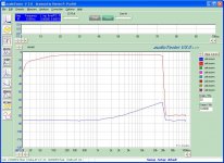
I found the audio isolation transformer I was looking for. I'd swear this was a radio shack 600:600ohm transformer for telephone interface. However, the plot looks too good from what I read about the transformer. Ignore the bottom trace. It is floating.
I'll try it on the input of the SC from the amp next time I get it on the workbench.
I'm working on my Sound Card Interface now. It has a fairly high harmonic content being induced in the output, and may be a bad IC, or ??? I'll post it in the SC thread.
I'll try it on the input of the SC from the amp next time I get it on the workbench.
I'm working on my Sound Card Interface now. It has a fairly high harmonic content being induced in the output, and may be a bad IC, or ??? I'll post it in the SC thread.
Attachments
I found the audio isolation transformer I was looking for. I'd swear this was a radio shack 600:600ohm transformer for telephone interface. However, the plot looks too good from what I read about the transformer. Ignore the bottom trace. It is floating.
I'm working on my Sound Card Interface now. It has a fairly high harmonic content being induced in the output, and may be a bad IC, or ??? I'll post it in the SC thread.
Don't expect miracles and expect limitations. telephone speechband 300-3000Hz. Some isolating transformers are designed for true 600R for such purpose. One can use below 300Hz only with miniscule AC volt drive.
r:-
Good point.
I'll test it with a 600Ohm load, however my intent was to use it with the high z input of the sound card to isolate the ground for testing and convert the single ended output of the amp to a differential signal. As such it will not be heavily loaded, and will be seeing 1Vrms max.
If it works it will show me a little more information on how my grounding is effecting noise, and if it works it may be worth it to purchase a couple better transformers. If not, well I may still learn something.
Come to think about it; some old companies of yesteryear did some darned good quality speechband telecom transformers with exceptional low insertion and distortion losses and could get far lower published frequencies. This was mentioned a few yrs ago in the forums, that someone was getting good results. Can't quite get my finger on it who did this but it was sourced in the US. Jensen ? could be.
richy
richy
Don't expect miracles and expect limitations. telephone speechband 300-3000Hz. Some isolating transformers are designed for true 600R for such purpose. One can use below 300Hz only with miniscule AC volt drive.
r:-
Here's the performance of the transformers in an HP353A Patch Panel:
An externally hosted image should be here but it was not working when we last tested it.
Quite good, I would say, considering that they can be had for next to nothing at hamfests. The Jensen JT-123 is close to flat from 2Hz to 200kHz but will set you back over $80.
- Status
- This old topic is closed. If you want to reopen this topic, contact a moderator using the "Report Post" button.
- Home
- Amplifiers
- Tubes / Valves
- THD, s/n and IM noisy measurements