Help!
I am experiencing problems trying to take FFT readings (s/n, THD, IM, etc) of a single triode gain stage 6NP1 AV 30.
My problem is the high background noise level I see when I run the amp with the reference return connected to chassis ground which is tied to safety earth (green wire on power plug). Reference return is tied to chassis ground via two anti-parallel 1N4007s.
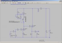
First figure is LT spice of the amp circuit.
I am running Audiotester V3.0 in an Asus A7N8X-VM400 as my shop computer 512MB RAM (1GB on order), with a GeForce FX5500, and no other peripherals (printer, scanner, etc) added or external connections other than a keyboard, monitor and my local network for access to the internet (tried disconnecting network and no effect).
I’ve verified the first power drop from the service entrance (circuit breaker box) to my workbench, and even added a second power drop just to be able to isolate the UUT (“Unit Under Test”) from the rest of my test equipment.
Finally I added a run of 10AWG ground wire from the service entrance ground bus to the work bench as an additional ground to test with (hopefully inductively isolated from power so as not to pick up common mode noise). Changing power drops makes no difference, and the additional ground makes very little difference.
Common/ground at the service entrance is tied to a 1” copper water pipe (per National Electric Code), and there is near 100yards of the 1” copper pipe that runs to the water meter, so I should have a good earth ground.
I’m using 6’ of RG174/U to connect to the input and output of the M-Audio Audiophile192 sound card.
I use a 10:1 resistive divider on the output of the sound card to the input of the UUT to allow me to run M-192 near -18dB output level to maintain a higher signal to noise ratio on the output from the sound card. The output of the sound card is adjusted to give a 1.0Vrms output from the UUT back to the sound card input.
The output of the gain stage is buffered with a cathode follower as I have seen loading issues when driving the sound card vs HP333A Distortion analyzer. (Is this an acceptable way of buffering? Would a FET source follower be better? Something else?).
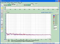
Loopback of the M-192 to itself shows a fairly clean plot (plot 1).
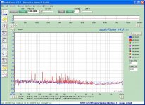
With the M-192 output off to the UUT and the UUD driving the M-192 input (filament but no B+) there is a lot of noise already present. This noise seems to be pretty broad banded although 60Hz and its harmonics are also pretty strong. (plot 2)
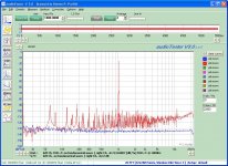
Turning on the 1KHz output and B+ results in a significant increase in noise level with a s/n of only -62dB and THD of 0.0807 which for a single gain stage seems pretty poor to me. (plot 3).
Last night I shout off all the CFLs in the house to see if they were a problem, but did not see any difference in the plots.
At least out to 300Hz there seems to be a lot of harmonic content from the 60Hz mains. Beyond that I can’t tell if the noise is related to power line harmonics or not, but if I have 300Hz within 5dB of 60Hz it looks to me like I have a serious line noise problem.
I’ve tried a line filter (and noted the specs don’t show any attenuation below about 40KHz so it is useless), and I’ve tried an Isolation transformer in attempts to isolate the UUT. Neither helped.
Any ideas on how to rule out noise from the computer?
What else can I do to isolate the noise and get a clean measurement?
I am experiencing problems trying to take FFT readings (s/n, THD, IM, etc) of a single triode gain stage 6NP1 AV 30.
My problem is the high background noise level I see when I run the amp with the reference return connected to chassis ground which is tied to safety earth (green wire on power plug). Reference return is tied to chassis ground via two anti-parallel 1N4007s.
First figure is LT spice of the amp circuit.
I am running Audiotester V3.0 in an Asus A7N8X-VM400 as my shop computer 512MB RAM (1GB on order), with a GeForce FX5500, and no other peripherals (printer, scanner, etc) added or external connections other than a keyboard, monitor and my local network for access to the internet (tried disconnecting network and no effect).
I’ve verified the first power drop from the service entrance (circuit breaker box) to my workbench, and even added a second power drop just to be able to isolate the UUT (“Unit Under Test”) from the rest of my test equipment.
Finally I added a run of 10AWG ground wire from the service entrance ground bus to the work bench as an additional ground to test with (hopefully inductively isolated from power so as not to pick up common mode noise). Changing power drops makes no difference, and the additional ground makes very little difference.
Common/ground at the service entrance is tied to a 1” copper water pipe (per National Electric Code), and there is near 100yards of the 1” copper pipe that runs to the water meter, so I should have a good earth ground.
I’m using 6’ of RG174/U to connect to the input and output of the M-Audio Audiophile192 sound card.
I use a 10:1 resistive divider on the output of the sound card to the input of the UUT to allow me to run M-192 near -18dB output level to maintain a higher signal to noise ratio on the output from the sound card. The output of the sound card is adjusted to give a 1.0Vrms output from the UUT back to the sound card input.
The output of the gain stage is buffered with a cathode follower as I have seen loading issues when driving the sound card vs HP333A Distortion analyzer. (Is this an acceptable way of buffering? Would a FET source follower be better? Something else?).
Loopback of the M-192 to itself shows a fairly clean plot (plot 1).
With the M-192 output off to the UUT and the UUD driving the M-192 input (filament but no B+) there is a lot of noise already present. This noise seems to be pretty broad banded although 60Hz and its harmonics are also pretty strong. (plot 2)
Turning on the 1KHz output and B+ results in a significant increase in noise level with a s/n of only -62dB and THD of 0.0807 which for a single gain stage seems pretty poor to me. (plot 3).
Last night I shout off all the CFLs in the house to see if they were a problem, but did not see any difference in the plots.
At least out to 300Hz there seems to be a lot of harmonic content from the 60Hz mains. Beyond that I can’t tell if the noise is related to power line harmonics or not, but if I have 300Hz within 5dB of 60Hz it looks to me like I have a serious line noise problem.
I’ve tried a line filter (and noted the specs don’t show any attenuation below about 40KHz so it is useless), and I’ve tried an Isolation transformer in attempts to isolate the UUT. Neither helped.
Any ideas on how to rule out noise from the computer?
What else can I do to isolate the noise and get a clean measurement?
Attachments
There's a lot of potential sources for the noise (note that it's not a lot of noise- it's mostly sub -100dB). The computer itself, with its radiation being picked up by the interconnects. Lights, especially CFLs (you turned yours off, but were there any others nearby?). The unit under test acting as an antenna. Nearby motors. Refrigerators.
I saw a big difference in that sort of hash when I used an input transformer on my preamp, FWIW.
I saw a big difference in that sort of hash when I used an input transformer on my preamp, FWIW.
Your results look normal if you are doing a single ended measurement with the M-Audio card. I get similar results.
If you want to do a clean measurement you need to make a balanced probe setup. Connect the + input from the sound card to the preamp output as you are currently doing. Connect the - input from the sound card to the output signal ground of the preamp.
By using both inputs from the sound card you are measuring the voltage output of the preamp and subtracting any noise that is on the signal ground.
The down side to making measurements with a high performance sound card is you quickly learn that it is a loosing proposition to expect clean signal transfer using single ended connections between different audio devices. Based on the experience of trying to make clean measurements on the bench with single ended cabling, all connections in my main music system are balanced.
Also, for the safety of the sound card you need at minimum to setup clamp diodes to prevent over voltage input from damaging the sound card input opamp. The input of the M-Audio card has no protection on the input- unless you consider a 5K series resistor on the inputs of the 5532 opamp protection...
If you are planning on using the sound card for measurement purposes you should build some sort of interface box to to buffer the signal, provide attenuation/gain, and protect the sound card. Pete Millet's input buffer project is nice. I designed a 2 channel fully balanced buffer/attenuator interface 5 years ago that is indispensable on the bench. After I become jobless in September I may pursue offering up a semi kit like Pete has.
Gary
What is the impedance of the 10:1 voltage divider? THings I do to reduce noise is to run cables as fart apart from each other as possible, and when they cross od it at 90 degrees. Use shielded signal cable. I also use Pete's sound card interface which makes it better.
Reality is that maybe the circuit is picking up the noise. The loopback, providing it is of similar impedance, is showing you what you have from the computer and soundcard.
P.S. Gary is right. I do most of my measurments balanced as well.
Reality is that maybe the circuit is picking up the noise. The loopback, providing it is of similar impedance, is showing you what you have from the computer and soundcard.
P.S. Gary is right. I do most of my measurments balanced as well.
Coincidentally (or not) I just went through the same set of issues to get my measurement noise floor below 100db.
My ADDA converter is an Alesis AI-3 which uses ADAT lightpipe to/from the computer so there is no ground loop there.
First, I did a loopback test and noticed as you did that the analog levels must be kept below about 1VRMS (even on pro audio gear like the AI-3) or the A/D and D/A will add it's own harmonic distortion.
Then when I hooked it up to an amp circuit for testing, there was power supply noise everywhere. I was using an external bench supply with it's own AC ground that was creating a noise current loop ("ground loop") due to the multiple ground connections in the wiring of the test harness.
Before I took the time to think it through, I first tried as you did to add an additional brute-force ground, which made things worse.
Then I back-tracked and started probing with a scpope on the amp with no signal. I found that 100mv of noise was appearing at the amp's input terminals.
My power supply was floating over 100mV of noise across a length of 16 gauge wire (power cable ground wiring) between the power supply and the ADDA box.
The solution for me was to put an isolation transformer in the AC line to the bench supply and connect the bench supply ground to the amp ground. What I did was in fact create a star ground on my workbench at the amp power connector for all of the AC and signal returns.
Voila!
Michael
Attachments
Take a look at Pete Milletts sound card interface, this is what you need to do in order to make good, repeatable (and sound card safe) measurements using your sound card.
I am using this with an M-Audio 24192 and Audio Tester 2.4 (I'll upgrade to 3.0 shortly - looks way better.)
Pete's thread is here: http://www.diyaudio.com/forums/tubes-valves/155405-test-measurement-interface-soundcard.html
This takes care of a lot of the sort of issues you are dealing with.
Ground loops and radiation from the computer and monitor (somewhat less of an issue with LCD monitors, a bear with CRTs - not that I have any except for my TV now).
Mike's suggestions regarding star ground and isolation transformer will also help a great deal. Do not succumb to the temptation to float the PC, the PSU in many PCs has appreciable leakage current and you could create a minor or not so minor hazard.
OT: Due to a ground wiring error in my house perpetrated by a previous resident I nearly got zapped by my PC... Old house, no safety ground available at the outlet used to power our computers, and this individual tied the neutral to the ground pin on the socket - 16ga knob and tube wiring to basement had appreciable IR drop on the neutral so I touched something that was grounded and got zapped.. The house has been completely rewired since and has a dedicated 20A circuit just for computer hardware..
Last edited:
Thanks all. Any other suggestions / observations are welcome.
I built one of Pete's interfaces, but I need to debug a distortion problem I'm seeing with it. I'll hook it up tonight and try to track it down, probably a bad op amp.
I'll also try diff input by adding a second connection from the low input of the M-192 to ground.
I was going to try an old radio shack 600:600 ohm transformer to convert single end to diff and run that, but I think I threw it out. RS does not carry them locally although they are listed on the web. It would have been a cheap test up to around 5KHz.
Transformers seem to be a bit of a pricy solution, but would they work well to help eliminate common mode noise if used at the amp for se to diff conversion? Logic seems to say they would.
The voltage divider is a 10K and 1K resistor as I didn't want to load the output too much. I realize it is 11:1 not 10:1 but I can adjust the M-192 output so I get 1Vrms out of the UUT which is what I want to test at.
I turned off every CFL in the house, and have 100M of power line to my transformer , but after looking up Power Line Communications on the internet I see they use up to 450KHz for communications, so that may not matter in terms of attenuation.
My other thought was to try a UPS for isolation, but figured it would probably produce as much switching noise if not more.
Last edited:
Thanks, Kevin
I agree wholeheartedly; don't float anything!
The soundcard interface is a nice start, but as pointed out, there is a gain structure issue with soundcards that is not addressed in the Millett design.
Single ended can work fine with a good star ground, but differential balanced will also deal with the radiated noise. Also, it's not always very easy to create a single star point on the bench. Every piece of gear would need an isolation transformer or isolated, seperately ground-able inputs and outputs.
Buffering with CF etc. is not sufficient. Galvanic isolation is needed without breaking the safety ground, hence the transformer and star point. It's not even clear to me that balanced differential I/O alone would solve the problem in all cases.
But by all means, safety first!
Michael
Michael,
If I follow what you are saying, to do the star ground you use ground isolation plugs on all the test equipment, and connect a ground from each to a single point on your bench, then connect it to the chassis of your UUT, and connnect the chassis to ground. Is this correct.
What about the PC, since it has the sound card in it. Should I treat it the same way?
I have a 600W isolation transformer (Not autotransformer) that I can use to isolate everything from ground. I just need to be sure I have a secure ground on each peice of test equipment tied to the single point ground.
Unfortunatly I'm still using a CRT based monitor in the workshop.
Transformers seem to be a bit of a pricy solution, but would they work well to help eliminate common mode noise if used at the amp for se to diff conversion? Logic seems to say they would.
My other thought was to try a UPS for isolation, but figured it would probably produce as much switching noise if not more.
Isolation transformers are cheap and reusable.
My AC power comes from inverters and they are extremely noisy. They are clean compared to a lot of other sources but there is a high harmonic content. One day I'll publish an FFT of my line power...
However, I think if I can make my audio gear clean in spite of my power line harmonics and switching noise, I have a piece of gear that will be quiet in almost any environment. I also use a Sola resonant CVT when I need clean AC.
michael
Michael,
If I follow what you are saying, to do the star ground you use ground isolation plugs on all the test equipment, and connect a ground from each to a single point on your bench, then connect it to the chassis of your UUT, and connnect the chassis to ground. Is this correct.
What about the PC, since it has the sound card in it. Should I treat it the same way?
I have a 600W isolation transformer (Not autotransformer) that I can use to isolate everything from ground. I just need to be sure I have a secure ground on each peice of test equipment tied to the single point ground.
Unfortunatly I'm still using a CRT based monitor in the workshop.
I don't own any cheater plugs that I know of... But that's the basic idea. Provide a good ground lug on the bench somewhere and make a secure ground connection from the equipment to the ground lug. Make a permanent connection from the incoming AC ground to this point (or a connection guaranteed to be connected and disconencted along with a single point of AC power). I hardwired my isolation transformer connections because I don't want a ground getting lifted if an AC plug comes out. This requires some care to be thorough and safe.
The good news is maybe not all of your equipment needs to be isolated. The first step is to use a scope on your existing setup to figure out where the noise is coming from and where it's getting injected into your signal path. 80db below 1 volt doesn't sound like much noise but you should be able to see it with a 1X probe.
Edit; a couple more random thoughts
Using balanced differential I/O does not give one a pass on grounding. it does shift the problem to a more subtle domain, e.g. what's the common mode impedance of my generator output circuit? which takes even more skill to sort out. Many so-called balanced differential circuits out there have surprisingly low impedance to ground. Yes, the designers should know better...
You really only need to isolate the local noise sources to get most of the benefit. Given a choice, it's best to remove the noise rather than float everything on the same noise. Again, it boils down to whether you want to solve gross issues or subtle ones.
Last edited:
I use notebook PCs for my measurements, preferably running off battery. This avoids most noise problems.
When using the built-in sound I/O, the noise floor will only be around -100dB compared to the 130dB in a premium sound-card, but good enough for most of my purposes.
Attachment is a PP power amp.
SveinB.
When using the built-in sound I/O, the noise floor will only be around -100dB compared to the 130dB in a premium sound-card, but good enough for most of my purposes.
Attachment is a PP power amp.
SveinB.
Attachments
Since I have th 10AWG ground wire straight from the service entrance, I could use that and mount a ground lug on the work bench. That would give me a known good perminant ground. I think regular ground in 12-2 w/ ground is 14AWG so the 10AWG might have an advantage.
80dB down from 1Vrms should be around 100uVrms. That will be difficult to see, but not impossible.
I guess I need to look at each peice of equipment to see how it is wired internally to determine how to proceed on setting up the isolation transformers. I may have a third 60W unit some where. That would be one 600W, one 200W, and one 60W. The ones comming up at the scrap sale are around 600W ea.
I use notebook PCs for my measurements, preferably running off battery. This avoids most noise problems.
When using the built-in sound I/O, the noise floor will only be around -100dB compared to the 130dB in a premium sound-card, but good enough for most of my purposes.
Attachment is a PP power amp.
SveinB.
That's pretty good resolution for a laptop sound card. You do need the battery; with the typical AC adapter, now required in many locations to pass the ground through, these things are useless for audio when AC-connected.
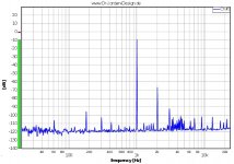
Looks like you're on 100Hz power. Here's an example of the ripple intermodulation often referred to; sideband energy at f+100 and f-100 Hz, -60db
Edit; Sorry that would be 50 Hz power, 100Hz ripple. Be curious to see the effect of a SS ripple reducer in the B+
Cheers,
Michael
Last edited:
Transformers seem to be a bit of a pricy solution, but would they work well to help eliminate common mode noise if used at the amp for se to diff conversion? Logic seems to say they would.
An IPT works better than an OPT, but both work better than nothing. http://www.jensen-transformers.com/an/an003.pdf
Check Edcor for inexpensive ($9) line transformers.
Looks like you're on 100Hz power. Here's an example of the ripple intermodulation often referred to; sideband energy at f+100 and f-100 Hz, -60db
Edit; Sorry that would be 50 Hz power, 100Hz ripple. Be curious to see the effect of a SS ripple reducer in the B+
Cheers,
Michael
The IM is produced by the LTP driver. Cleaning up the negative voltage and LED reference for the CCS and better filtering of B+ reduces the IM.
Svein
Attachments
Which series of Edcor?
WSM
EDCOR - Browse Series
Only issue is that if they don't have them on hand, they can take a few weeks.
Well, I connected the 10AWG ground wire to a barrier strip on the bench so I have a single point ground reference. Then I set up isolation transformers for the computer and monitor since the computer is the most likely source of noise. I can see it on the sound card output even though in loop back it looks clean.
It made a slight improvement.
Now that I have the bench cleaned off I'll wire both inputs of the sound card so I can use one for the ground reference input.
Next order to Edcor I'll get a couple of isolation transformers to play with. Thanks dsavitsk.
Latest plot shows lower distortion and higher s/n so I'm moving in the right direction.
Which brings me to the question of what standard to test to?
what weighting? "C weighted"? I turned it on.
What cut off frequency for the lower cutoff ? I've been using the default 200Hz.
Is there any standard for comparison purposes or is it just a matter of 'whatever floats your boat'?
Attachments

Last edited:
- Status
- This old topic is closed. If you want to reopen this topic, contact a moderator using the "Report Post" button.
- Home
- Amplifiers
- Tubes / Valves
- THD, s/n and IM noisy measurements