Morning @Xoc1,I looked at some of my models and I suggest that the inner panel angle is too steep - causing the initial expansion.
Appreciate the response. We're going to take a look at generating the hornpath of this iteration of the TH18, and will post here when it's complete.
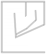
With respect to the inner panel (too steep), it's current at 36deg - see below. This matches your sketch in post #2963 as far as we can see. Are we missing something here?
I know this forum is a decade old, but is there a CNC cut file floating around for this build?I just got my 18sound drivers from loudspeakersplus.com....ordered tuesday morning had them by friday evening! They are beasts!
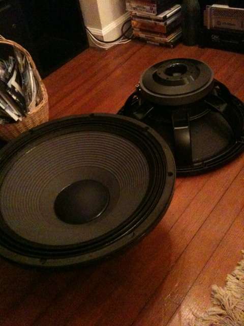
(2) 18lw2400's which will be used in two TH-18 tapped horns, design courtesy of Xoc1 (Thanks again for all the info/effort you put into this!!) Also thanks to Djim for his help and patience through my questions with the design/corner bracing etc etc.
This thread is for anyone who builds his box. I figured I would start because I think I am one of the first to do so!
I will go pick up some good high quality 3/4" Birch tomorrow and get started on this. Pictures to follow asap!!
Here is the Sketch plus a nice cut list...
View attachment 226593

Extra bracing which Djim suggested...
An externally hosted image should be here but it was not working when we last tested it.[/URL]
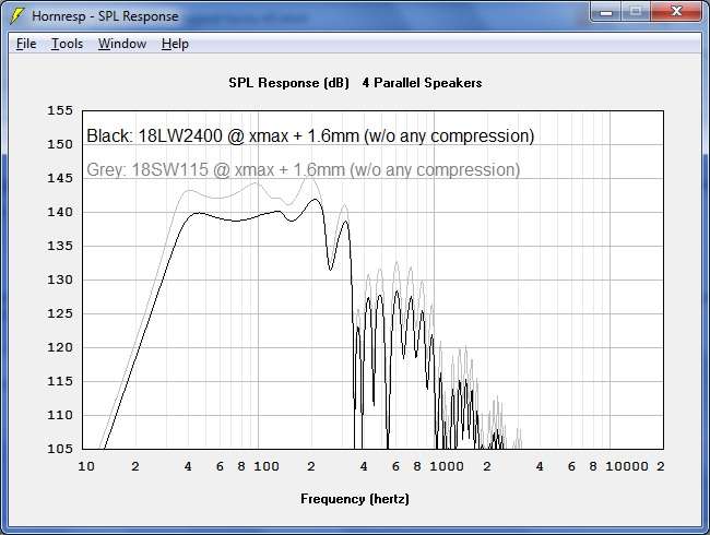
Now I am pretty sure that the point of this design was for 4 cabinets to be Flat to 35hz. I am starting with only two because of cost, not just for drivers/wood but amp power needed to drive them as well. These are some powerful cabinets and depending on which driver you choose to load them with, they can take a serious amount of wattage!
There are a ton of different drivers which have been simmed for this design, I think most have been simmed for the cabinet without the corner reflectors, but still the same external volume cabinet.
Here is a sim for 4 cabs at xmax + with the 18 sound 2400 drivers...
Morning @Xoc1,
Appreciate the response. We're going to take a look at generating the hornpath of this iteration of the TH18, and will post here when it's complete.
With respect to the inner panel (too steep), it's current at 36deg - see below. This matches your sketch in post #2963 as far as we can see. Are we missing something here?
View attachment 1104452
Hello Freek Audio,
The link below has a very similar design layout that you can adjust the dimensions to achieve TH18 from Xoc1. The cone correction is similar but not the same, with proposed design you have one lass interface to glue. It may worth to evaluate. The horn path is already done for you and will adjust automatically.
https://freeloudspeakerplan.rf.gd/pages/th-ss2.htm
'...I am pretty sure that the point of this design was for 4 cabinets to be Flat to 35hz.' -wllgregory1214
I presume the designed, being modeled as 1/4 wave, would necessitate four. But I have been incorrect often, particularly with...cars and women. But, that is another topic.
Q: Long Ago, In A Brain Better Populated By Brain Cells...I drew a folded horn using basic (back-of-the-napkin) calculations for a 100hz to 400hz horn using 1/2 wavelength. I did so to avert the early roll-off observable when a 1/4 wavelength modeled horn is placed in what is actually closer to a 1/2 space (far away from side walls, considerably far from what would be the rear wall [think, art installation], and very likely, in a large room with a double-door [or quadruple] entrance opened to the outdoors). Of course, this was only theory (on paper), so experimentation did not occur.
One concern still bothers me:
If such a horn (or a pair), were to be placed in an area, say, 20' x 40', could I expect some undesirable effects for having designed using 1/2 wavelength (as oppose to the more common 1/4 wavelength)? (I concluded...'unlikely', but I would appreciate a deduction, however brief, from the better versed).
I may have the opportunity to build the horn in 2023, thus my inquiry.
Anyone?
Dresden,
I'm not answering your questions but actually my curiosity was aroused, why you want a 100 to 400hz horn? ,I mean at those FREQS and with the gain of a folded horn you will need....what a 4:1 ratio for subs? , One of your low mid horns over 4 th18's?
My humble knowledge about sub theory that I have learned on this forum just crashedNburned.
☹️
Not much difference between the low end of multiple tapped horns compared to a single, they do not require the mouth exit to be large in relation to wavelength to work well. That said, a tapped horn would not work as well as a front loaded horn for 100-400Hz.'...I am pretty sure that the point of this design was for 4 cabinets to be Flat to 35hz.' -wllgregory1214
The undesirable response effects will stem from room modes, not horn design.Q: Long Ago, In A Brain Better Populated By Brain Cells...I drew a folded horn using basic (back-of-the-napkin) calculations for a 100hz to 400hz horn using 1/2 wavelength.
If such a horn (or a pair), were to be placed in an area, say, 20' x 40', could I expect some undesirable effects for having designed using 1/2 wavelength (as oppose to the more common 1/4 wavelength)? (I concluded...'unlikely', but I would appreciate a deduction, however brief, from the better versed).
The 100-400hz range would serve as a mid-low horn in an open or semi-open space. In listening tests, I concluded 400hz a frequency sufficiently non-critical (in terms of direction), affording me the ability of placing higher frequency horns in an horizontal off-set manner (if need be), without much concern.Dresden,
I'm not answering your questions but actually my curiosity was aroused, why you want a 100 to 400hz horn? ,I mean at those FREQS and with the gain of a folded horn you will need....what a 4:1 ratio for subs? , One of your low mid horns over 4 th18's?
My humble knowledge about sub theory that I have learned on this forum just crashedNburned.
☹️
Of course, to some, anything more than 250hz or 300hz would not be acceptable.
Indeed.Not much difference between the low end of multiple tapped horns compared to a single, they do not require the mouth exit to be large in relation to wavelength to work well. That said, a tapped horn would not work as well as a front loaded horn for 100-400Hz.
The undesirable response effects will stem from room modes, not horn design.
I have a few faital 10FH520 drivers I have not used. Perhaps not ideal, but I will attempt one horn with one driver. A sub, as you noted, may indeed demand considerably more power or drivers (assuming same efficiency) for each horn, to be an adequate complement.Dresden,
I'm not answering your questions but actually my curiosity was aroused, why you want a 100 to 400hz horn? ,I mean at those FREQS and with the gain of a folded horn you will need....what a 4:1 ratio for subs? , One of your low mid horns over 4 th18's?
My humble knowledge about sub theory that I have learned on this forum just crashedNburned.
☹️
Since I am aiming more toward music (as oppose to movies), designing a sub flat to 40hz (instead of below 20hz) may help with size and efficiency.
The Xmax is too low 7.9Hi everyone! I wonder if this driver is man enough for this Th design ?
View attachment 1128580
But the BL is on the high side ,
What brand and model is it?
It's ak18dsw from TtspeakerThe Xmax is too low 7.9
But the BL is on the high side ,
What brand and model is it?
hard to tell how xmax is defined here.... if its pure geometrical xmax, its not too bad. The total power is not a lot with 600 Watts... Looking at the magnet here:
http://en.ttspeaker.com/products_detail/productId=212.html
I´d suspect that BL is either not valid or that the VC is very short and xmax is determined by the typical equation... VAS is quite hight, too.... My feeling tells me, its not too suited..
I´d fire up hornresp or WiniSD, input the given parameters and cross-check if BL etc.. add up....
Considering the real displacement will be lower then predicted from Hornresp you could also add 20%~30% over it. You can go even further regarding the distortion you consider acceptable but of course i would require to check the diaphragm displacement at Peak Power condition (if I remember well, 4 * AES RMS power) and it needs to be lower then X-mech.
Thanks sir @BP1Fanatic

Ah ok thanksConsidering the real displacement will be lower then predicted from Hornresp you could also add 20%~30% over it. You can go even further regarding the distortion you consider acceptable but of course i would require to check the diaphragm displacement at Peak Power condition (if I remember well, 4 * AES RMS power) and it needs to be lower then X-mech.
You're welcome!Thanks sir @BP1Fanatic
Hey everyone.
I having a bit of a nightmare with my build! Im hoping someone can clarify, potentially, what my issue could be!
Short story is I've been building these boxes since 2015 and I'm on my third build now.
On my 2nd build, I was getting quite a lot of wood slapping noises at high(ish) excursion so I thought it was just a bad build so my third was pretty much the same build but with much more glue and with every corner and joint covered in sealant, making sure there was no air leakage!.
Unfortunately, the slapping noise is worse in my latest build and it's uber frustrating and confusing. I then thought it was the drivers but the drivers check out fine. I'm using BMS 18N862 drivers.
Here's a video to the issue.
I tested the drivers outside the baffle as well to make sure there were no strange noises coming from the subs themselves.
Then I thought I made the baffle hole a little too small and so the driver was hitting the wood but it wasn't that! I also tried a test at 5hz to really get the excursion going on the drivers(not too much power) just to see if the drivers really were hitting anything and that checked out fine too.
It happens at quite a specific frequency range which now says to me it's the design of the box. It's most prominent between 60-80hz and it's a real slapper of a noise!
I've used the original design spec which was for a much less powerful driver so I'm wondering if I've simply used the wrong dimensions for my BMS drivers?
It's been braced more than enough but I'm just so confused at this point! I just can't see how any part is flexing in any way to create such a horrible sound!
Any help would be amazing!
Thanks,
Sal
- Home
- Loudspeakers
- Subwoofers
- TH-18 Flat to 35hz! (Xoc1's design)