Member
Joined 2009
Paid Member
That looks neat Andreas - does it mean that no change to layout, it can be just installed without change - I didn't see this double-headed part in the Digikey catalogue.
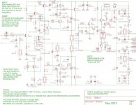
Dear Ranchu - updated schematic for you is attached. Look carefully for errors. If I have the Opto device wired backwards for example then it ain't gonna work or be something easy to fix without new pcb.
By the way, I suggest blue coloured pcb to match colour of flags where inspiration for this design originated")
Dear Ranchu - updated schematic for you is attached. Look carefully for errors. If I have the Opto device wired backwards for example then it ain't gonna work or be something easy to fix without new pcb.
By the way, I suggest blue coloured pcb to match colour of flags where inspiration for this design originated
Attachments
Last edited:
Member
Joined 2009
Paid Member
Here's the parts list as it stands. I've included everything to build the "full monty" version using SMT parts only. (I can include the TH equivalents where catered for on the layout, if you think its important).
Anyway have a look - interested in your comments.
Some additional comments regarding the BOM - thanks for helping out with this by the way. I've been checking out some of the part numbers you listed and so far they are looking good. For the resistors, can you get the Stackpole 1/2W such as RNCP1206FTD100RCT-ND (or something with 1/2W rating in 1206) ?
Choice of parts will partly depend on power rail voltages. I have a +/-50V supply but if I were to lower my sights to +/-40V things would be different. First off, the BD139/40 devices are rated up to Ceo max of 80V (I think Rod says they are OK for use in a P3a with +/- 42V rails). The VAS device can swing almost from rail to rail so it should be rated for the full rail spread. The BD139/40 doesn't meet this requirement if using +/-50V. Also the heat dissipation of the VAS depends on the rail voltage and current through the VAS and although we could attach a small piece of alumininium to the VAS device for cooling we might prefer to reduce VAS current slightly by using higher valued resistors in the collector load. I've already increased it from 3k3 to 3k9 in the schematic.
What voltage for the power rails should we be aiming for ?
I'll give some thought to which parts we might want to have a few different values on hand. As you say, with resistors, they are so cheap you may as well get a few extra values. I'd get extra TO-126 parts to use as 'washers' under the pcb too.
You want some of these too: BER169-ND
For the input I was thinking of this: WM4200-ND
Anyhow, I uploaded a re-export from Eagle of the parts list in case this helps match up to the updated schematic.
Attachments
Last edited:
By the way, I suggest blue coloured pcb to match colour of flags where inspiration for this design originated
Hi Gareth,
Cannot more to agree with the color chosen, It'll end with a nice
little blueish shine which will for sure match the sound of Mr. Rods design.
Cheers,
A.
Member
Joined 2009
Paid Member
Hi Andreas - also a match to the colour of your (Euro) flag
Rachu - you had trouble finding ceramic caps sized '1812' ? I figure that the larger sized parts (not 1206) are more robust? The rail caps should be XR7 rather than np0 (less likely to ring with trace inductance) whilst the zobel being closer to the audio path should be np0 type. The zobel can take some abuse so the larger size is good for dissipation. However, board flex will crack ceramic caps so if we have a plan to be giving the boards grief with plugging and unplugging connectors...
fyi - I found that I have to select 'Surface Mount, MLCC' and not just 'surface mount'. Try: 1276-3406-1-ND for the XR7 parts, try: 445-2356-1-ND. These are both 100V parts.
Last edited:
Gareth, thanks for the updated schematic with matching component identifiers. This is most useful. I'll revise the BOM tonight and incorporate your suggestions.
I've used the BD139/140 reliably with 42V rails but this is pushing the limit and anything higher will need a different part. I've assumed the low power version will reliably handle 35V rails or 42V if used only with 8R loads. The high power one would be fine on 42V into 4R or 50V into 8R.
I'll spec the MJE15030/31 for use with the 50V version unless you have a better idea.
Member
Joined 2009
Paid Member
I've never used a TO-126 part at 50V before so I'll go with your suggestion which I'm sure will be good.
It would also have been nice to have some input from Sakis.
I added a few more resistors to the design I posted earlier which weren't that obvious but mostly across the filter capacitors to provide a leakage path to discharge them - just a safety precaution and a habit because it's always conceivable they didn't get a chance to discharge if the amp was broken in some way and +/-50V is no laughing matter for those who will dare to go this high.
I'll check in again tomorrow.
Hi guys...
Digikey have no stock of the MJE15030/31 combo so instead I've spec'd the MJE15034/35 combo for high voltage versions.
These are TO-220 packaged semis - is there room on the board? It looks tight around Q5 & Q7...
The other problem we have is that the drivers get pretty hot at higher voltages and lower Z loads. I think heatsinks for the drivers will be a necessity when driving into 4R with 42V rails or 50V rails into pretty much any load.
Member
Joined 2009
Paid Member
Heatsink for Drivers: I ran the Spice simulation with 4 Ohm load and something around 200W dissipated into this load at 1kHz sine wave. The drivers were running at less than 200mW dissipation. Is this too high ? Remember that the drivers do not need to sink excessive base current from the output device like in P3a because the maximum current through the output BJT is limited - at some point the MOSFET takes over and it doesn't require the driver to sink any base current although it must drive the gate capacitance. However, the power dissipation of the emitter resistors was very high and likely would blow them up if sustained if the fuses on the power rails didn't blow fast enough. Please run my spice simulation to confirm. Perhaps there are circumstances where they will be stressed too high such as with very inductive loads ???
I will have to double check but the only resistor > 100K is the nested feedback from VAS to feedback node which I put in as 470k. It can be low power. It is also optional and we may want to try different values. As this resistor gives some local feedback from the output of the VAS it reduces the global feedback. We may only want to use it if using the enhanced VAS design which creates a lot more open loop gain. We may want to reduce the resistor to a lower value too.
Yes, I believe TO-220 parts could be accommodated. The larger parts may affect stability (capacitances) ?
Attachments
Last edited:
Member
Joined 2009
Paid Member
Member
Joined 2009
Paid Member
The drivers would dissipate several W of power with no MOSFETs and clipped heavily into 4R and assuming no rail fuses blow and the emitter resistors survive too. I don't think Rod ever designed the P3a to survive that kind of abuse, maybe that's why he had the P27 version with double outputs and an overload protection circuit (of sorts). My MOSFETs are a kind of protection circuit (of sorts) if you think about it.
For the drivers did you consider:
MJE340 and MJE350. TO-126 packages. Rated to 300V. And thankfully have the same pin-out as the BD139/40 pair. I have found these to be highly recommended on the internet, and they are available from Digikey (.com) at good prices and they have lots of stock. I think they look perfect
Last edited:
Member
Joined 2009
Paid Member
Hi Rachu,
Thanks for taking the time on this.
I've made some suggested changes to the BOM. With these changes all the existing pcb footprints are preserved. See attached.
We're almost there - what we didn't include are some extra values for experimentation. The compensation caps C4,5,6 - would be handy to have extra values. You know - maybe some through-hole ceramics would be useful for that, you can cut the leads short (reduce inductance) and tack them onto the pads to do quick experiments before settling on final values to install fully. The through hole parts are easier to remove if you have only one soldering iron whereas the SMT parts need two irons or a special iron for the task (I use two irons).
The other values that might need to be changed are hard to predict so it's simply a good idea to have extra values of resistors on hand. And it's not unusual to blow up a few parts trying things out so spare parts are handy.
Attachments
We're almost there - what we didn't include are some extra values for experimentation. The compensation caps C4,5,6 - would be handy to have extra values. You know - maybe some through-hole ceramics would be useful for that, you can cut the leads short (reduce inductance) and tack them onto the pads to do quick experiments before settling on final values to install fully. The through hole parts are easier to remove if you have only one soldering iron whereas the SMT parts need two irons or a special iron for the task (I use two irons).
The other values that might need to be changed are hard to predict so it's simply a good idea to have extra values of resistors on hand. And it's not unusual to blow up a few parts trying things out so spare parts are handy.
Hello Gareth,
My I point You to these very reliable small buggers as they are not sub mm ones
but theirs reliability are one of the best from my past 15 yrs. experience in similar critically places even for Audio.
Some Special Features:
Pulse duty construction
Maximum pulse rise time:
1000 V/µsec for pulses equal to the rated voltage
Close tolerances up to ±2.5%
(±1% on request)
Very low dissipation factor
Negative capacitance change
versus temperature
Very low dielectric absorption
According to RoHS 2002/95/EC
Typical Applications
For high frequency applications e.g.
Sample and hold
Timing
LC-Filtering
Oscillating circuits
Audio equipment
More to read: DATA
My best regards,
A.
FKP are a really good choice
who wrote that for Wima?................. I point You to these very reliable small buggers.......................
They have the less than and greater than back to front !
- Home
- Amplifiers
- Solid State
- TGM8 - my best amplifier, incredible bass, clear highs, no fatigue (inspired by Rod Elliot P3a)