Great work ")
I'm taking a look at the BOM and have a couple of questions...
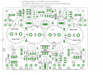
Input cap pin pitch is 5mm and it's proving problematic finding an electro that size without ridiculously high voltage for this position. I can spec a bipolar Nichicon ES 10u 16V that has pin pitch and can diameter of 2mm and 5mm, respectively. If you want to keep the option for film caps (5mm pitch) then I suggest you lay down 3 pads spaced 2.5mm each to accommodate either option properly.
Are the zeners TH or 1206? Hard to tell from the diagram.
I'm taking a look at the BOM and have a couple of questions...
Input cap pin pitch is 5mm and it's proving problematic finding an electro that size without ridiculously high voltage for this position. I can spec a bipolar Nichicon ES 10u 16V that has pin pitch and can diameter of 2mm and 5mm, respectively. If you want to keep the option for film caps (5mm pitch) then I suggest you lay down 3 pads spaced 2.5mm each to accommodate either option properly.
Are the zeners TH or 1206? Hard to tell from the diagram.
Member
Joined 2009
Paid Member
Great work
I'm taking a look at the BOM and have a couple of questions...
Input cap pin pitch is 5mm and it's proving problematic finding an electro that size without ridiculously high voltage for this position. I can spec a bipolar Nichicon ES 10u 16V that has pin pitch and can diameter of 2mm and 5mm, respectively. If you want to keep the option for film caps (5mm pitch) then I suggest you lay down 3 pads spaced 2.5mm each to accommodate either option properly.
Are the zeners TH or 1206? Hard to tell from the diagram.
I just did a quick look on Digikey website (.com), I found 20 choices of bipolar caps that are 10mm diameter with 5mm pin spacing. Anyhow, it's a good suggestion to generate a footprint that allows for some different options for pin-spacing.
All diodes (except the LED) are SOD123 which is a fairly standard and common surface mount package size.
I can generate a parts list directly from Eagle. I've uploaded a preliminary list as an example - let me know if this is helpful as I can add more detail within Eagle so that it is relatively easy to generate an up to date listing.
Attachments
You mean like this ?
Hello Bigun,
I do quick reposition of the Caps. fuses, resistors as I made a suggestion in my post #98.
Pls. see att. img.
I'd keep the OP TRs Decouple caps as near the TRs pins as possible.
With my best regards
A.
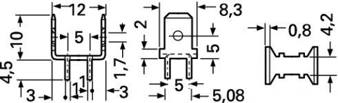
PS. The SMD Fuse + Holder in att. PDF
Attachments
Member
Joined 2009
Paid Member
HI Smiley,
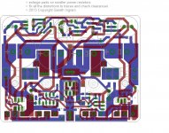
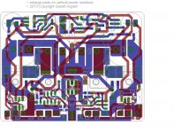
The attached shows you where the traces are so you can get a better idea of why I didn't move things as you suggested - I did look at some of the options but there were other compromises needed. Please look for errors.
Mounting holes - the outer ones are sized so that the screws will secure the pcb to the heatsink through the power device, the inner ones are to clear the screws and will not contribute to holding the pcb down. This is what I did in TGM7 to allow more tolerance on drilling holes in the heatsink but as this board is larger perhaps all 4 holes should be small enough to allow the screws to hold the pcb down ?
Anyhow, I'm starting to get the feeling that this layout needs to reach a conclusion - I'd started out with the intention that it would be finalized this week in order to contain the scope of work and Friday is fast approaching...
Attachments
Last edited:
Member
Joined 2009
Paid Member
My suggestion is to use these guys: ITEAD Studio 2Layer Color PCB 10cm x 10cm Max
I've used them before with no issues.
The timing of the order is flexible, but I do want to reach a conclusion on the layout very shortly. After that you guys can influence when the boards are ordered - for example it may be sensible to wait whilst a couple of you check the circuit and develop a BOM for your local supplier to ensure the parts sizes etc are good. Perhaps decide on a few details such as size of mounting holes, whether the big caps are to be snap-in type etc.
Perhaps decide on a few details such as size of mounting holes, whether the big caps are to be snap-in type etc.
Hello Gareth,
You made very elegant and really versatile PCB Board, nothing more to add.
Maybe to put on-top on each OP TR same 10 mm x 10 mm x 2 mm kind of plastic pads to little distant the PCB from direct contact to the OP TRs to reject heat transfer onto PCB and still provide enough physical contact to firmly secure board via M3 screws from the top true the PCB board with an additional support of the 10 mm x 1mm round metal pad on-top of the outers screw PCB fixings to firmly fix the PCB on top of OP Trs.
Congratulations on Yours Great will to make this little AMP a new bright light to all Diyers.


With my best regards,
A
Member
Joined 2009
Paid Member
Hi Smiley, a small picture of what you describe might be helpful but I think I know what you are suggesting. These plastic pads sounds like a great idea - do you know where to buy them from ? I was thinking that TO-126 transistors are so cheap now that we just cut off their legs and use them as washers !!!
Do you think it's OK if all 4 mounting holes are used to hold the pcb, it will require accurate drilling of the heatsink which is harder for some people - or if I just have 2 of the mounting holes for pcb and the other two just clearance to fit a screwdriver through ?
Do you think it's OK if all 4 mounting holes are used to hold the pcb, it will require accurate drilling of the heatsink which is harder for some people - or if I just have 2 of the mounting holes for pcb and the other two just clearance to fit a screwdriver through ?
Hello Gareth,
I have a 30 x 20 cm veroboard that is without coper on each side from an other project of making
some small boxes for a cars fuel enrichment before enters into the injectors.
It is the same material as odinary PCB (FR4) and has excellent mech. and thermal properties.
Using a little heavier scissors for making the pieces needed is a child play to cut them and to drill a 3,2 mm hole true them.
I'd definitely use all four screws for fixing the PCB in place and at the same time.
I'd add the same size of 10 mm x 10 mm x 1 mm thick rubber pieces directly on top of the plastic or vero spacers to even further reduce the vibrations of the PCB being mounted and to provide some spring load to the screws at the same time.
I was quite surprised how much vibrations are present on the PCB or on the other parts of the AMP itself sourcing from Main reservoir caps, OP transistors and the vibrations picked up from the sound sources in the same place when music is reproduced. All this is of course added as a mechanical sources of the time different distortions to the main output (speakers) and to additional smear the fine details even at the moderate listening levels. I did a laser measurement on one of my amps with the tool we use for vibration analyses of the racing engines and gearboxes and the results was surprised and give me a lot of thinking to me.
It cost nothing and right now where You are at the design phase You can easily implement them.
I do this on my old & trusty V24 old timers mono blocks and the sound improvement was quite evident
It's a time to catch some slip here,
With my best regards,
A.
Member
Joined 2009
Paid Member
Hi Smiley,
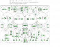
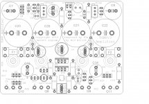
Here's an image of the underside of the board. Still a few items to clean up. But I've placed some outlines to show you how much room there is around the mounting holes underneath. It's a very crowded board and you don't get a lot of space for washers to be in contact with the underside of the board before they interfere with through-hole parts and SMT parts.
Edit: uploaded revised layout with option of installing the resistors from the CRC filter under the board as Smiley suggested.
Here's an image of the underside of the board. Still a few items to clean up. But I've placed some outlines to show you how much room there is around the mounting holes underneath. It's a very crowded board and you don't get a lot of space for washers to be in contact with the underside of the board before they interfere with through-hole parts and SMT parts.
This sounds far more interesting than amplifiers !I did a laser measurement on one of my amps with the tool we use for vibration analyses of the racing engines and gearboxes and ...
Edit: uploaded revised layout with option of installing the resistors from the CRC filter under the board as Smiley suggested.
Attachments
Last edited:
Bigun,
I think that PMI uses Design Spark software for pcb design. It's free software and there is no dimensions limit. I downloaded it but there is no libraries for parts and these must be created separately. I am not skilled for pcb design, just curious, so I downloaded it to see how it looks. May be you could use it for bigger pcbs than free version of Eagle could fit?
I think that PMI uses Design Spark software for pcb design. It's free software and there is no dimensions limit. I downloaded it but there is no libraries for parts and these must be created separately. I am not skilled for pcb design, just curious, so I downloaded it to see how it looks. May be you could use it for bigger pcbs than free version of Eagle could fit?
Member
Joined 2009
Paid Member
I think that PMI uses Design Spark software for pcb design. It's free software ...
Thanks for passing that along. Only thing is, the learning curve can be pretty steep and now that I am familiar with Eagle I'm reluctant to change. But it's OK - we're limited by heatsink size here too so a bigger board would only be of interest if making a stereo version.
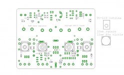
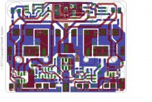
I turned the Quickfit connectors around 90 degrees as this may be easier to access when they are close to the big cap.
Keep looking for issues.
Attachments
Last edited:
Bigun, I'm having dramas sourcing a 420p C0G in a 1206 package. There is one mica variant available on Digikey, although stock is low. Can I safely substitute the far more readily available 470p value here?
I noticed you've reduced the front end filter (C7, C8) from 330u to 100u. Is that what you wanted? I further note you've specified the KZ audio series here. Nichicon HE is excellent and has the advantage of slightly smaller can and corresponding lead spacing (8mm, 3.5mm). The BOM will reflect your preference for the Muse caps unless you advise otherwise.
I noticed you've reduced the front end filter (C7, C8) from 330u to 100u. Is that what you wanted? I further note you've specified the KZ audio series here. Nichicon HE is excellent and has the advantage of slightly smaller can and corresponding lead spacing (8mm, 3.5mm). The BOM will reflect your preference for the Muse caps unless you advise otherwise.
Member
Joined 2009
Paid Member
Hi,
The thing is, the Full Monty version has all sorts of parts in it, it's become more of an experimental platform that allows us to build the basic P3a (if we can find parts the right size) and then explore from there.
For example, the basic P3a does not use two-pole compensation. The 420p in 1206 size that you asked about is part of the two-pole-compensation option. The value definitely needs to be reviewed and does not need to be exact - but will likely have to be adjusted once built so having a few parts of different values in the parts-bin would help. Or we can not bother with two-pole compensation, leave that for another day.
The front filter caps were chosen partly for their physical size and pin spacing as needed to make the pcb layout work when we shoe-horned in those 4 large filter caps. Some folk may feel that using Nichicon Muse is more important for the sound than having a larger value of capacitance, but this again is a choice for the builder since there are larger value non-audio caps that can be used in this spot.
I suggest we tackle the BOM in stages. Stage 1 - make sure we can find parts to build the basic P3a on this board. It may be wise to build it like this first - there are many pitfalls and risks which we should eliminate before moving on to the more advanced elements. We will need to check that the basic design has stable bias, can be compensated so as not to oscillate, has good bias stability, that parts don't need additional heatsinking and that it sounds good. If we can't get it to this milestone then the pcb probably has to be re-spun.
Be prepared, I've always found that interesting and rewarding projects find it necessary to put me through some drama along the way !
Last edited:
Here's the parts list as it stands. I've included everything to build the "full monty" version using SMT parts only. (I can include the TH equivalents where catered for on the layout, if you think its important).
The BOM includes the parts for both VAS schemes for those that want to experiment (the parts cost is peanuts) except for the 420p as noted above.
You can't just walk into an electronics store in Australia and buy SMT caps/resistors. Shipping an order is expensive and I expect few constructors will have a stockpile of SMT values onhand, like they would for TH. So if you think there are some other values worth adding to the BOM for experimentation it would be good to do so (the parts cost is next to nil).
Anyway have a look - interested in your comments.
Attachments
Member
Joined 2009
Paid Member
I turned the Quickfit connectors around 90 degrees as this may be easier to access when they are close to the big cap.
Hello Gareth,
For the TO126 stile PCB board spacers I fully agree wit Yours latest reposition as the space is really tight. The spacers should be cut from any kind of material at hand to survive some 150 deg C temp.
Can You add another GND Quickfit connector beside the current one or a Dual one should be used also for SPKR GND connect This way both SPKR OP wires should be twisted from the PCB and routed this way to the OP connector on the chassis.
The PCB is become really neat and compact.
Congrats,
Best Regards,
A.
Member
Joined 2009
Paid Member
Hi Andreas,
Well I like the idea of keeping the wiring simple as you suggest. But where to fit the extra quickfit ? if you look there isn't an obvious place since it must not short front to backside of pcb and there is very little space to fit your fingers in there to push on and pull off the connectors - note how the connectors are crowded by the large capacitors and the solid state relay TO-220 devices. Anyhow - open to suggestions as to how to do this. Otherwise it isn't too bad, we just have to connect two earth wires to the one quick fit connector for gnd.
Well I like the idea of keeping the wiring simple as you suggest. But where to fit the extra quickfit ? if you look there isn't an obvious place since it must not short front to backside of pcb and there is very little space to fit your fingers in there to push on and pull off the connectors - note how the connectors are crowded by the large capacitors and the solid state relay TO-220 devices. Anyhow - open to suggestions as to how to do this. Otherwise it isn't too bad, we just have to connect two earth wires to the one quick fit connector for gnd.
But where to fit the extra quickfit ?
Hi Gareth,
I mean at the same place as this one, it'll use almost same space, later with a little help of a small pliers or with little tinner fingers could be managed.
With my best regards,
A.
Attachments
- Home
- Amplifiers
- Solid State
- TGM8 - my best amplifier, incredible bass, clear highs, no fatigue (inspired by Rod Elliot P3a)