Member
Joined 2009
Paid Member
I've given up trying to squeeze a decent power supply into the small chassis that I'm using for my power amp. I've bought a box off of ePay and I'm going to build a power supply into that. It will power my power-amp over a short cable and also provide power to a separate pre-amp.
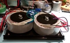
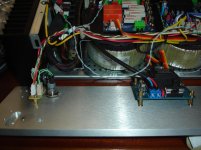
So far I drilled out the base-plate and mounted the Toroids. There are two, one for the L channel, one for the R channel. I'll be keeping the power grounds separate but both will be connected to mains earth through a ground-loop interruptor (diodes). Photo shows progress.
There will be rectifier and caps to go in the box too. The transformers are 36Va.c. and I expect around 42Vd.c. after rectification.
Not yet sure what kind of connectors to use for the dc supply umbilical to the power amp. Ideally, 7 pins, conveying V+, V-, GND for L and R channel plus a spare. I have some 7-pin DIN sockets and DIN plugs which would fit nicely but they aren't the largest most robust connectors. However, being on-hand they are likely what will be used.
Attachments
Last edited:
Member
Joined 2009
Paid Member
Member
Joined 2009
Paid Member
Loss-of-mains-detection ? - No, the amplifier will have it's own circuit for that. It will detect loss of dc and shut off the amplifier output. The dc rails collapse pretty quickly but it's an approach that appears to have worked in past projects.
A 5Vdc would be nice to have. Will give it some thought.
mains dc-blocking ? - I haven't provided for this. If I need this, I may not have space to include it. Do you have a recommended approach/circuit ?
A 5Vdc would be nice to have. Will give it some thought.
mains dc-blocking ? - I haven't provided for this. If I need this, I may not have space to include it. Do you have a recommended approach/circuit ?
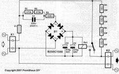
Many threads here on DIYA about mains DC blocking. One big controversy in them is: do you, or don't you, need to install two electrolytics in series? Rod Elliott's article emphatically screams YES. However, Bryston (Canadian high end mfr) ships product without two electrolytics in series, yet their gear is famously reliable. Tell me what to do, Obi-Wan?! I'm scared and I want Someone Else to make this decision for me??!!
Suggest you Think Hard about how to / whether to / connect the "ground" of the always on 5V DC supply.
Suggest you Think Hard about how to / whether to / connect the "ground" of the always on 5V DC supply.
Hi Bigun
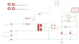
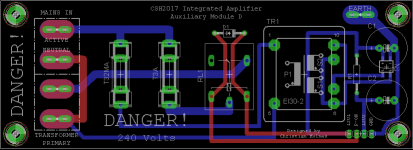
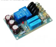
Here's the sch and pcb for a simple mains input module that you might find interesting. Its designed to sit at the back corner of the amplifier chassis, in front of the IEC socket.
It holds a small onboard 9V transformer that powers a housekeeping microcontroller and 12V for the main transformer control relay and smoothed 12V used to drive the signal relays used to select the source/line input.
My main transformer is a 200VA with modest smoothing caps behind it and I've never felt the need for inrush limiting, but if you are using bigger transformers this is definitely something to think about.
The main transformer secondaries go directly to the main amplifier pcb, which includes output muting/speaker protection circuitry and drops out on loss of AC. AC is sensed after the secondary fuses.
Attachments
Bigun,
I suggest you use the Amphenol 7pin 20amp LTW series connector between the power supply and the amplifier.
Don't forget that you need to extend the chassis earth from the power supply chassis to the
amplifier chassis, so you will need 7 pins and not just 6. I think you can get a cable from Amphenol that has the plug pre terminated with a reasonable length of cable.
Regards,
Paul Bysouth
Attachments

Member
Joined 2009
Paid Member
Hi Bigun
Here's the sch and pcb for a simple mains input module that you might find interesting.
Hey, that looks really neat !
Attached photo of what I have used in the past and no issues. It's not as elegant as your solution and has less functionality but in my desire to get something moving here I already hit the 'buy' button and have one on it's way to me from the East.
Attachments
Member
Joined 2009
Paid Member
calm down......... I do think Bryston knows what they are doing. I used to own their BP60 integrated amp. I've never had trouble with misbehaving toroids.Tell me what to do, Obi-Wan?! I'm scared and I want Someone Else to make this decision for me??!!
Attachments

Last edited:
Member
Joined 2009
Paid Member
Thanks for the suggestion Paul, I like this brand, they use the small versions at my work place. Digikey carries the larger one's that I'll need,so that's convenient for me.Bigun,
I suggest you use the Amphenol
Member
Joined 2009
Paid Member
some progress, it's very slow, but day job and house job....
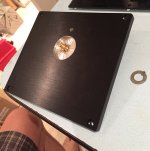
I powered up the drill press and created a rebate to mount the on/off switch on the front panel of the power supply along with a 5mm dia hole for an indicator LED. I'll hunt down a piece of 5mm perspex rod to stick in the front and poke in a 5mm LED from the back - the plate is 8mm thick!
I powered up the drill press and created a rebate to mount the on/off switch on the front panel of the power supply along with a 5mm dia hole for an indicator LED. I'll hunt down a piece of 5mm perspex rod to stick in the front and poke in a 5mm LED from the back - the plate is 8mm thick!
Attachments
Member
Joined 2009
Paid Member
Hi Gareth i'm looking for the same external power supply solution but using separate unit for R&L channels.I've given up trying to squeeze a decent power supply into the small chassis that I'm using for my power amp. I've bought a box off of ePay and I'm going to build a power supply into that. It will power my power-amp over a short cable and also provide power to a separate pre-amp.
So far I drilled out the base-plate and mounted the Toroids. There are two, one for the L channel, one for the R channel. I'll be keeping the power grounds separate but both will be connected to mains earth through a ground-loop interruptor (diodes). Photo shows progress.
There will be rectifier and caps to go in the box too. The transformers are 36Va.c. and I expect around 42Vd.c. after rectification.
Not yet sure what kind of connectors to use for the dc supply umbilical to the power amp. Ideally, 7 pins, conveying V+, V-, GND for L and R channel plus a spare. I have some 7-pin DIN sockets and DIN plugs which would fit nicely but they aren't the largest most robust connectors. However, being on-hand they are likely what will be used.
Isn't possible to afford the cost of power supplies for those amplifiers.

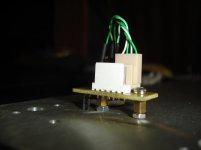
My solution for LED indicator and on-off switch in my SA2015 amplifier.
3.5mm blid hole and 3mm through hole.
Attachments
Last edited:
Member
Joined 2009
Paid Member
I didn't think about having separate units for L & R, that would be twice the work !
With one box you can turn it all on with one master on/off switch. Inside the box I have dual-mono construction (except the on/off switch!) with everything separate between the channels. There is a separate L&R ground, they will each have a ground loop safety network to the chassis and mains safety earth.
I need to make some stand-offs for pcb's. I am thinking to use some wooden dowel, it's a good insulator, inexpensive and can cut to length.
I use 1/4" nylon air tubing. No hole drilling. Cut to length with Chanllock air line cutters. Hole clears a 10-32 screw, which can have washer on top and elastic stop nut on the bottom (for permanance). 6-32 screws require smaller holes, can support up to a coupla pounds.I need to make some stand-offs for pcb's. I am thinking to use some wooden dowel, it's a good insulator, inexpensive and can cut to length.
I use Jones plugs for this kind of high current connection. 600 v 6A rated, solder terminals heavy enought to take 14 ga. DIN7 is not rated for much current. Cut the square hole with a 9/64" drill bit around the edges, then a Stanley carbide hacksaw to connect the dots.
I buy the CB's at electronicsurplus in NY or apexelec in LA, along with the cinch type terminal strips the MOS supressors can solder to. Freight from either is minimum $10, so come up with $50 of stuff you want before pushing the buy button.
I put MOS surge supressor after the CB or fuse and before the transformer. ATX supplies have them, those are also toroids they are protecting. Factory VFD drives have them too, mostly mine are salvage from dead ones. But they are about $.26 each in the 14 mm size (used in VFD's). Those mile away lightning strikes that make the incandescent lamp filaments ring go into those instead of your 600 V rated transformer wires.
Last edited:
You could glue the wooden dowels to the corners of a piece of 1/8 inch thick plywood (also called "hardboard" and/or "utility panel") before drilling. Now you've got a nice solid wooden insulator between the bottom of your PCB, and the metal chassis. No possibility of shorting to the chassis, no how no way, even if a random dot of solder or wire breaks free and rattles around inside the cabinet.
Of course this does increase the capacitance between the traces on the bottom of the board, and the metal chassis. The dielectric coefficient of wood is ~2.5 and the dielectric coefficient of air is 1.0. Your stack will probably be PCB--->(0.25" air)--->(0.125" wood)--->chassis metal, so you'll need to take a weighted geometric mean between the epsilon_r of wood and the epsilon_r of air.
Of course this does increase the capacitance between the traces on the bottom of the board, and the metal chassis. The dielectric coefficient of wood is ~2.5 and the dielectric coefficient of air is 1.0. Your stack will probably be PCB--->(0.25" air)--->(0.125" wood)--->chassis metal, so you'll need to take a weighted geometric mean between the epsilon_r of wood and the epsilon_r of air.
- Status
- This old topic is closed. If you want to reopen this topic, contact a moderator using the "Report Post" button.
- Home
- Amplifiers
- Power Supplies
- TGM - an external PSU for power-amp