Member
Joined 2009
Paid Member
Thanks for the encouragement guys.
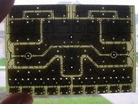
And now that I have sorted out the pcb making, it's actually enjoyable
It turns out that the EI transformer I wanted to use doesn't quite fit into the chasis. The drawings say it should, but the reality of how it's manufactured means I'd have to make some 'modifications'. So I will likely end up with a donut instead. At least it will be lighter.
We're getting closer...
Attachments
Member
Joined 2009
Paid Member
MJL21193 said:I think a pair of your smoothing caps are backwards.
oops! - yes C8 and C14 will have to be installed counter to the 'silk screen'. Your eyes are not so bad after all. Can you see the extra hole in the pcb ?
Member
Joined 2009
Paid Member
Yes, it's dangerous, I could be thinking about the next project already !
Well, off work this week (due to economy we have a forced shutdown for 1 week per qtr so far this year)...
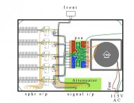
I'll need to decide where things should be bolted down in the box soon. Trying to keep incompatible wires away from each other or crossing at 90degrees. Keep rectifiers close to Trafo but far from amps. Keep psu board near to amps. Put amps where heatsinks can be bolted to side of box - if it ain't cool enough I can replace them with something beefy without re-doing the chasis. Keep 115V AC in a corner away from prying fingers. Anything else ?
Well, off work this week (due to economy we have a forced shutdown for 1 week per qtr so far this year)...
I'll need to decide where things should be bolted down in the box soon. Trying to keep incompatible wires away from each other or crossing at 90degrees. Keep rectifiers close to Trafo but far from amps. Keep psu board near to amps. Put amps where heatsinks can be bolted to side of box - if it ain't cool enough I can replace them with something beefy without re-doing the chasis. Keep 115V AC in a corner away from prying fingers. Anything else ?
Attachments
Member
Joined 2009
Paid Member
Member
Joined 2009
Paid Member
he he he !
[...look at C4, it has three legs ]
]
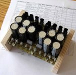
Well we have made some progress again today...I checked it twice, but my gosh this thing better not launch the caps!
some idiot ordered 10 fuse holders for 10 fuses, but each fuse needs 2 holders - oh well !
[...look at C4, it has three legs
]Well we have made some progress again today...I checked it twice, but my gosh this thing better not launch the caps!
some idiot ordered 10 fuse holders for 10 fuses, but each fuse needs 2 holders - oh well !
Attachments
Member
Joined 2009
Paid Member

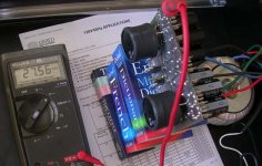
By Bigun - Good news - the PSU works, first time thankfully. No exploding capacitors.
Having fun yet.
") You are lucky with only 27V , not in the "one flash and your ash" realm yet.
You are lucky with only 27V , not in the "one flash and your ash" realm yet.Very good work for your first one , It took me 3 "rounds" to get as refined as your work. I've done one,(reversed polarity) at 30v ,
swelled cap , smoke , maybe a "pop". 70-80v is not as forgiving....
BOOM-POW
 (duck).
OS
Member
Joined 2009
Paid Member
Thanks for the compliment OS. I'm quite pleased about it, although it is a dead simple circuit, it's the first I've ever built - for some reason my interest in electronics as a kid was mostly pulling things apart!
Chasis work is proceeding slowly, it's not the bit I'm most interested in. Grinding paint off pieces of chasis where they screw together to ensure earth connections to all pieces is a bit painful. Still, I have all the speaker binding posts mounted now.
Somebody was kind enough to give me a bag full of yellow LED's - I'm considering breaking from tradition and using a non-blue power indicator.
And, if things keep progressing, I will eventually have a platform to plug the amplifier prototype into so that it can be played with, broken, fixed and otherwise brought to a final design.
Member
Joined 2009
Paid Member
Any opinions on multi-channel volume control ?
I decided that the Lightspeed LDR approach is the best, but matching 12 devices is prohibitive. simplifying to a shunt system helps as then I need only 6, but I think it's an approach that exceeds the requirements of my HT project. I will use it in my next project, which will be stereo, when I can lavish more attention on just 2 channels and benefit from what I've learned so far. Well we'll see.
For 6 channels (5 amp channels + flow through to the active sub) I don't fancy finding an expensive 6-ganged pot.
Anybody used the digital potentiometers ?
I'm thinking of a fixed series resistor per channel and a digital resistor in the shunt position. The signal is less affected this way, to my understanding.
I would look at something like this for a simple up/down 100k resistor {http://search.digikey.com/scripts/DkSearch/dksus.dll?Detail&name=AD5227BUJZ100RLCT-ND}
together with a shaft encoder {http://search.digikey.com/scripts/DkSearch/dksus.dll?Detail&name=GH3071-ND}
and that's it !
thoughts ???
Member
Joined 2009
Paid Member
Signals are planned to come from Sony Blu-Ray S550.
The Blu-Ray guys have realized that many people already have Receivers which can't decode the higher quality sound tracks on BluRay and can't be upgraded via firmware. To cater to these people several Blu-Ray players incorporate full decoding on board. With the advances in decoder techniques etc. it's easier to do this in a integrated package now than it was before. Consequently this Blu-Ray player is able to decode and output full analogue 7.1 via RCA connectors. I believe the quality of the DAC's is pretty good. It also allows for some bass management, time delay, output level and speaker size to be set. These functions remove the need for a Receiver but they don't provide for convenient volume control.
The RCA outputs are quoted as "2V 10k Ohm" which I take to mean peak to peak max is 2V and the output impedance is 10k.
Not having a Receiver I plan to take the output from the BD player into the TGM via a suitable attenuator.
I was tempted to skip a volume control, I figured that I only need a toggle switch on the front panel that reads 'loud' and 'quiet' as these seem to me as the only relevant options
Member
Joined 2009
Paid Member
Here's a more graphical description of my hair brained proposal. It doesn't explain everything, but the key thing to note is the little diagram showing the 2-bit output from the encoder and that if you rotate it clockwise the timing goes from left to right, if you rotate anti-clockwise it therefore goes from right to left. And this makes all the difference !
There are some details to be understood, such as the power-up sequence for the digital potentiometer.
The cost looks more than reasonable for this approach, although there's no through-hole package available for the digi-pot (I don't consider this an obstacle).
However, it's volatile, resets to half-way on power cycling. That could be an issue, have to think about that.
But will it work ???
Attachments
Bigun said:Here's a more graphical description of my hair brained proposal. It doesn't explain everything, but the key thing to note is the little diagram showing the 2-bit output from the encoder and that if you rotate it clockwise the timing goes from left to right, if you rotate anti-clockwise it therefore goes from right to left. And this makes all the difference !
There are some details to be understood, such as the power-up sequence for the digital potentiometer.
The cost looks more than reasonable for this approach, although there's no through-hole package available for the digi-pot (I don't consider this an obstacle).
However, it's volatile, resets to half-way on power cycling. That could be an issue, have to think about that.
But will it work ???
Looking at the AD5227 datasheet, the analogue signal range permissible on pins A,B,W is restricted to between GND and VDD. This means that your signal input (and signal ground) lines will need to be biased to around VDD/2 = 2.5V with respect to the IC's GND for maximum usable voltage swing.
There is a significant capacitance (140pF) between pins A and GND for this device. The resistor shown between 'signal i/p' and 'signal o/p' needs to be selected such that this capacitance doesn't degrade the high frequency performance too much. For example, if this resistor is 5.6K ohms, there will be a 3dB attenuation at 200KHz. Why not wire pins A,B,W as a conventional potentiometer?
As the device only draws 3 microamps from the supply, battery-backup could be investigated in order to overcome the 50% power-reset setting limitation.
Regards,
Steve
Vishay has multi-ganged pots - stackable:
http://www.vishay.com/docs/51047/p9.pdf
Available at Digikey:
http://search.digikey.com/scripts/DkSearch/dksus.dll?Detail&name=P9A1-10K-ND
Might be a lot less hassle.
http://www.vishay.com/docs/51047/p9.pdf
Available at Digikey:
http://search.digikey.com/scripts/DkSearch/dksus.dll?Detail&name=P9A1-10K-ND
Might be a lot less hassle.
Member
Joined 2009
Paid Member
Very handy feedback guys.
Digital Pot:
=======
Looking at the part selection then, there may be a better, albeit slightly costlier option using the WMS7170100P-ND.
This offers a bit more resolution (100 linear steps), lower capacitance (30pF vs 140pf), non-volatile memory which I'll set as a one-time-programmable to minimum volume and as a bonus it comes in an easier to handle 8-pin DIP package. Updated schematic attached.
The need to put the voltage range in the right place shouldn't be too hard to arrange ?
Physical Pot:
========
I started off with this option, realizing I'll have to buy 3 dual-pots and then rebuild them into a 6-pot. These are plastic resistors and Vishay also make a cermet version which I think would be of better quality - but DigiKey don't carry this 'military grade' version.
The only reason I'm considering the digital potentiometer is because from what I've read, the physical pot is the worse choice for sound quality, the LDR's the best choice and everything else falls into the middle. People who have build relay controlled discrete resistor versions have been pleased with the sound quality increase over the physical pot.
Having not had the chance to compare however I'm at the mercy of my perceptions...
Attachments
Bigun said:
Physical Pot:
========
I started off with this option, realizing I'll have to buy 3 dual-pots and then rebuild them into a 6-pot.
Which are almost certainly guaranteed to work.
Bigun said:
These are plastic resistors and Vishay also make a cermet version which I think would be of better quality - but DigiKey don't carry this 'military grade' version.
If I'm not mistaken, Vishay makes quality parts - period. The P9A is for audio aps.
The P9S is for industrial (dirty, damp, chemical, etc.) use.
Bigun said:
The only reason I'm considering the digital potentiometer is because from what I've read, the physical pot is the worse choice for sound quality,
Having not had the chance to compare however I'm at the mercy of my perceptions...
Once again, believing everything that is written (especially here!) is a slippery slope.
Member
Joined 2009
Paid Member
MJL21193 said:Once again, believing everything that is written (especially here!) is a slippery slope.
Perhaps the wisest words for a newbie on this forum
- Status
- This old topic is closed. If you want to reopen this topic, contact a moderator using the "Report Post" button.
- Home
- Amplifiers
- Solid State
- TGM Amplifier ?