Member
Joined 2009
Paid Member
Kind friend found me a bench and power supply.
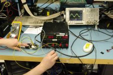
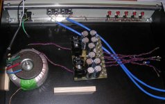
TGM1 was powered up for the first time. I made no adjustments, the q. current was around 80mA per rail. The bench supply could go no higher than around +/-21V. The voltages on the base of the output devices and driver devices was about right. The heatsink got quite warm and the current draw increased. I held the VBE device on top of the output device with my finger and the current draw fell back.
However, the heatsink was still pretty warm. I couldn't see oscillations with a scope, but it was hard to see really HF because a fan on the benchtop was contaminating everything (including the supply gnd).
So, first power up, no adjustments, output offset was -ve 30mV. Not bad eh?
Gave it a sine wave input and it was clipping - amplitude of input too high. You can see the input and output on the scope at 1KHz. The measured gain was 16. I will have to check the resistors but I think it was supposed to be around 14. Not bad.
I ran the frequency up to 100kHz, saw the output halve it's amplitude around 90kHz. A bit low maybe.
But there was no load on the output and there are wires everwhere. Also, at the lower supply rail voltage the current through the LTP will be quite small, no doubt the gm is not where it's supposed to be.
Anyhow, I'm quite pleased about the birth.
Attachments
It lives... cool.
Good deal. no  . 30mv is not bad for no LTP emitter degeneration. (this is the same as circuit?). You were lucky to have a lab supply with readouts (.09 = 90ma) I had to calculate with 2 sacrificial resistors (poor mans fuse).
That is a rather small test HS in the pix (good for drivers ,not op's)
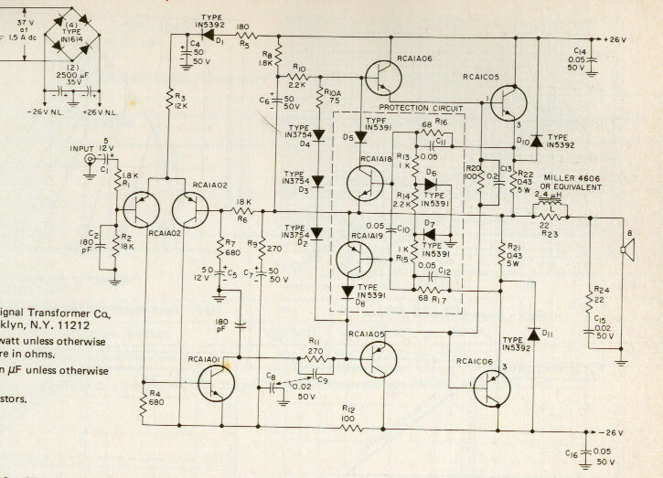
Are you still using the 100pF Cdom? Still , try some 10khz square waves, that will show you the "truth" as far as compensation goes.
Once you have it working to this stage , it is usually safe to give it it's final supply rails , change capacitor values to a certain point (tweaking), and finally listen to it. good work.
PS.Those look like very young hands?
OS
By BG - TGM1 was powered up for the first time.
Good deal.
no . 30mv is not bad for no LTP emitter degeneration. (this is the same as circuit?). You were lucky to have a lab supply with readouts (.09 = 90ma) I had to calculate with 2 sacrificial resistors (poor mans fuse).That is a rather small test HS in the pix (good for drivers ,not op's)
I ran the frequency up to 100kHz, saw the output halve it's amplitude around 90kHz. A bit low maybe.
Are you still using the 100pF Cdom? Still , try some 10khz square waves, that will show you the "truth" as far as compensation goes.
Once you have it working to this stage , it is usually safe to give it it's final supply rails , change capacitor values to a certain point (tweaking), and finally listen to it.
good work.PS.Those look like very young hands?
OS
Member
Joined 2009
Paid Member
Re: It lives... cool.
Yeah, my friend was really disappointed, he said he was only helping me because he thought something exciting involving smoke would happen. Yes, no emitter degeneration.
The HS was small. But the heatsinks I've made up aren't that big either (attached). I happened to have half a dozen metres of extruded heatsink and thought that the least I could do was to use some of it. According to the spec. sheet a 3" slice is around 1.67degC/W and I simply folded a 3" slice back on it'self to make a double sided HS. I don't expect ever to run this at full power (25W). It took some cutting, filing and swearing but I'm getting that sinking feeling this isn't going to cut-it (as usual in this hobby things don't seem to go right always)
By "Cdom" if you mean the capacitor I have on the VAS - this is 68pF. To 'play' with this value I will have to order more capacitors, although I have some 22pF I can try.
Yeah, surprised me too, I can assure you that my middle aged body is not properly represented here. I'm going to offer the camera owner a small sum for that lens
Originally posted by ostripper Good deal.
Yeah, my friend was really disappointed, he said he was only helping me because he thought something exciting involving smoke would happen. Yes, no emitter degeneration.
The HS was small. But the heatsinks I've made up aren't that big either (attached). I happened to have half a dozen metres of extruded heatsink and thought that the least I could do was to use some of it. According to the spec. sheet a 3" slice is around 1.67degC/W and I simply folded a 3" slice back on it'self to make a double sided HS. I don't expect ever to run this at full power (25W). It took some cutting, filing and swearing but I'm getting that sinking feeling this isn't going to cut-it (as usual in this hobby things don't seem to go right always)
Originally posted by ostripper Are you still using the 100pF Cdom? Still , try some 10khz square waves, that will show you the "truth" as far as compensation goes. Once you have it working to this stage , it is usually safe to give it it's final supply rails , change capacitor values to a certain point (tweaking), and finally listen to it.
By "Cdom" if you mean the capacitor I have on the VAS - this is 68pF. To 'play' with this value I will have to order more capacitors, although I have some 22pF I can try.
Originally posted by ostripper PS.Those look like very young hands?
Yeah, surprised me too, I can assure you that my middle aged body is not properly represented here. I'm going to offer the camera owner a small sum for that lens
Attachments
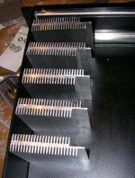
sheet a 3" slice is around 1.67degC/W and I simply folded a 3" slice back on it'self to make a double sided HS. I don't expect ever to run this at full power (25W)
If you keep your bias reasonable (60-70ma) , with only one pair of
OP's , that will work. What you have = 1 P4 heatsink (1.5c/w) , I ran 2 pairs on 2 with no gross thermal issues. ventilate them well with holes below and above (or a big hole with screens).
By "Cdom" if you mean the capacitor I have on the VAS - this is 68pF. To 'play' with this value I will have to order more capacitors, although I have some 22pF I can try.
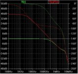
I have found 68pF to be the good middleground between performance and stability. (attached) -3db is around 100k and the unity gain point is 300k. What you tested with yours seems to be right on with the simulation(-3db @90khz). Beware ,22p will give overshoot and ringing (maybe even oscillation).
OS
Attachments
Member
Joined 2009
Paid Member
The plan is two devices per heatsink and we'll see how warm they get. The amp overall is not exactly over-engineered; there's little room to push it. The heatsinks are 'on the edge' of being sufficient and same goes for the power supply. In fact, the power supply may save the day by limiting the power that can be pushed into the heatsinks if all channels are going hard. This design is based on the fact that my speakers should not require a lot of juice (they're rated at 15W). We'll see. If it's a disaster I have an excuse to go bigger.
The 22pF caps are for the HF comp, from the VAS collector to LTP inverting input. I remember some advice on the forum regarding Cdom (Hugh ?) which suggested a range from 22pF (tizzy trebble) to 100pF (sluggish).
The HT project was possibly the wrong starting point, I was really planning to start with a chipamp, but then I ran across the AKSA amp. It's been a bit adventurous first time out the gate, I had assumed things would be simpler. On the upside, everything has turned out to be more interesting and support on the forum great.
I'm surprised the amp seems to have worked first time out, perhaps there's more below the surface to discover yet. I'm pleased the planned 'cool' LTP biass current seems to be holding up (1/2 mA).
Did you go to all the trouble of loading the amp design into simulation software for me ?
I'm surprised the amp seems to have worked first time out, perhaps there's more below the surface to discover yet. The surprise stems partly from the fact the supply rails are well below design and so the LTP bias must be small (with 39k biass resistor).
You would be surprised "how low" a amp like this works. My bootstrap amp has CCS's , but they will play music all the way down to under +-10 per rail. Every voltage and current in the amp collapses proportionately so the amp still works at greatly reduced voltages/currents, all the way down to the reference voltage of the sources.
You should be good to go...
 could put a 3-500R resistor at output and listen to a pair with headphones.. careful !!!
OS
Member
Joined 2009
Paid Member
Weird, your quote of my post doesn't match my post - looks like your post coincided with an edit I made and it all got muddled.
It's certainly time to try putting some music through it. A few bits of infrastructure to sort out first if that's going to happen at home this weekend - but things are moving !
It's certainly time to try putting some music through it. A few bits of infrastructure to sort out first if that's going to happen at home this weekend - but things are moving !
Good work Gareth,
Cheap test speakers can be had at Goodwill - pretty much disposable if they get nailed with DC.
You can attach a Zobel to see for sure if it is oscillating. The resistor will get hot.
A few power resistors in parallel will make a good dummy load - mine is 10 - 80ohm, 10 watt resistors between 2 pieces of CPU cooler heatsink.
Attachments
Member
Joined 2009
Paid Member
I think I will be brave enough to hook up the DIY speaker I made - can put a capacitor in output if I get nervous. But progress is very slow this weekend - firstly you never have the little bits you need, a missing bolt or nut and then all comes to a stop. A drill bit too big for the drill chuck means a round needle file has to be used. And then it's the sunshine, a BBQ (charcoal, none of this gas rubbish) is soon to be fired up in the backyard
Also, a friend just dropped by and left me with his new amplifier to burn-in. It's a Yaqin VK-2100 hybrid. Uses 1943/5200 ClassAB output stage with 6N1 tube front end (not in differential pair config). It is the first time I ever heard something with tubes. It sounds not at all bad I have to say. Detail and clarity is less than my Bryston, but it seems a little more 'fluid', especially with my Fostex ONKEN's, if I can use that as a description.
I am wondering if TGM4 is a hybrid amplifier ?????????
Also, I can see from Spice that TGM2 doesn't allow me to play with the harmonics in the same was as TGM1, especially regarding H3. I am thinking that if I fall in love with TGM1 that I should think instead for my next project to make it bi-amp with TGM1 on upper, TGM2 on lower ????????
Sorry, but I have to light coals....
Member
Joined 2009
Paid Member
ostripper said:...The new monster symasym has nuclear bass , but it is another amp. Both have all the others beat as far as midrange definition and HF detail (brushes , cymbals, etc.) That is why i said symasym = center channel , very forward vocal imaging.
The abomination has the same sound , same general topology , the VSOP also has this sound.. but the symasym is much simpler.
What is it about the symasym topology that gives these benefits ? What is affecting bass performance, it isn't just freq. response. Put it another way, where are the weaknesses in TGM1 ?
I still want to understand more about the benefits of improvements to the basic TGM1 and so I have used the LTSpice again - maybe this software isn't sufficient ?
I tried emitter degeneration of the VAS, of the LTP, I tried the LED/BJT source for the LTP instead of a simple resistor and I tried the complimentary LTP devices. Each change was explored on it's own. I can't say I saw a significant improvement in the distortion spectra in any one case. The combination of all of these changes is clear, but the simulations don't really illuminate things very much.
Member
Joined 2009
Paid Member
just in case it seems like I'm not doing anything, here's the chasis slowly coming along.
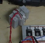
Added the wiring to the psu board, added a dozen turns to the donut for the power-on indicator LED, installed twisted pairs to the RCA connectors and added an earth bus to the speaker terminals (not as ideal as separate star earth connections but this will be upgraded if necessary).
Had to add a piece of wood to stabilize the chasis - it wasn't designed to have a Trafo bolted to the bottom plate so I had to anchor it to the chasis side.
Attachments
Gareth,
You have realize that relatively quickly.but the simulations don't really illuminate things very much.
Member
Joined 2009
Paid Member
I took the plunge and wired it up today. Volume control is the 'rescued' 50k pot with 10k fixed from wiper to gnd.
The dc offset was around 70mV but my LTP is not balanced with the current set up. The voltages on the output device emitters were out of whack (2:1).
Still, I was impatient and connected up my DIY MoonOnken speaker.
....nothing.
Turned up the volume and sound came forth. WOW.
I haven't been able to turn it off since
Many thanks to all the help received so far !
Member
Joined 2009
Paid Member
OS, You got it right - I was expecting to be replacing output devices by now
Thanks Lumba.
I got brave enough to wire it up to my PMC floorstanders. Two in parallel (effective 4 Ohm).
I can only compare it directly with my Bryston as that's what I have on hand. Bearing in mind that I chose the Bryston over KRELL, LINN and NAIM it's tough competition for the DIY amp. Even in this rough state it sounds to me like the TGM can compete. Too early to make an unbiassed appraisal but I'm very optimistic.
(assuming I can fix the very low level hiss&hum produced when the source is at zero output).
Heatsink seems to be doing the job.
I'll have to build another module so I can do AB comparisons whilst I tune it up.
Member
Joined 2009
Paid Member
Update...
I have modified the resistor values around the LTP because it was not well balanced and I hadn't updated them after I used a different rail voltage (slightly lower). I also put a DMM across the output emitter resistors and tuned the VBE for 27mV each, which is about 57mV through the output pair.
This cleaned up the sound. I can now compare my Bryston against TGM1, L channel vs R channel. Wow, they are so close. The bass of Bryston is very good, but I don't find TGM1 is less in comparison.
I tried a female vocal to listen specifically for sibilance on the 's' and I found the two amps identical in this regard. The Bryston is a bit cleaner, although it's really hard to find a difference. However, the TGM sounds smoother. I enjoy listening to the TGM more than the Bryston. I am not yet sure if I believe this, maybe too much 'DIY pride' affecting my subjective listening. Following advice I will get a scope on it and play with it some more.
In the meantime I am still exploring the TGM2. My latest version now adds a current sink to the VAS. It is influenced by Patchwork as well as Frugal. It's hard to see the benefits of all these changes in the sim and I am worried that it becomes more like a challenge to see how many more components I can add to TGM rather than keeping it simple (and listening tests get to be like The Emperors New Clothes). But I attach the latest, not quite optimized. I had to fiddle with the LTP resistors a bit since the base of the VAS now sits higher off the -ve rail. It's a more complex design to understand, I don't fully understand how these sub-circuits interact.
Distortion spectra looks much much better than TGM1, on paper that is. But my design goal is not necessarily low distortion, the goal is that I love the sound.
Attachments
By bigun - maybe too much 'DIY pride' affecting my subjective listening.
It is hard to compare amps , isn't it ? Listen to yours long term then go back to a OEM , see if you laugh. I listened to my new one for a month , found a sherwood discreet receiver (brand new/ w remote) hooked it up and it did not sound nearly as good (even had hiss
 ). "sibilance on the 's'" .. just white/pink noise. Try to hear the tongue hit the top of the mouth(small transient) before the "s" or "shhh".
CCS's - this also has to do with "thumps" , with properly chosen values a "CCS less" input differential can have almost no thump or a very small one. With a CCS and small value decoupling cap <100uf, NONE. On the original amp (1972 rca) there was a thump (I built one in 84')
Read all about the first amps.http://www.hilberink.nl/amps/amps0.htm The blameless , dx/aska are all old tech(72') , we just use better transistors.
My supersym is not too new either , both hitachi and elector (89') did this first. We should get together like carlos suggests and make one that will match the audiophile one (you know the one) without infringement AND with modern parts. I WILL have my 2 rear channels in the end.
 OS
OSMember
Joined 2009
Paid Member
Hi OS,
I'll check out that link.
I'm not sure if I have the experience to contribute but if this is an invitation to design a 'DIY Reference amp' then I will try to contribute. I'll have to wait and see what you have in mind, I have already started down the path of TGM2, not sure how many I can do in parallel so may have to choose
If you want to hijack the TGM2, maybe that is also an option.
I'm not sure if I have the experience to contribute but if this is an invitation to design a 'DIY Reference amp'
I don't have a lot of experience , nothing like bob Cordell , doug self ,or john curl , but this simple toy would great as a introductory offering to new constructors.
As far as experience(only Jimi Hendrix really has that
) , just the fact that you have one operational puts you in that league.What I have in mind is a amp that :
A. Can be used with rail voltages of 20- 45V without component changes. This is where a CCS works out well
.B.Can use a wide variety of devices (it's a big world - not everyone has everything) with only minor documented changes to the original design (BD vs KSA/2SA - carlos should calm down.)
C.physically allows upgrades , start out with cheap junkbox 2200-3300uf caps , PCB allows 10,000uf @50v as upper end. Extra pads for tweaking (compensation options) This way we can hint at the last few IP tweaks to get to the fancy kit level
. D.Sound quality, safety and durability. Results would vary depending on the individual's choice of A,B,and C , but managable with simulation/documentation.
Finally a name , people are fickle , one with a catchy name will psychologically sound better
I did offer carlos the answer to his fast device oscillation problem (1-22r/miller value change) , he saw it as "messin' with his baby". We have dozen or so new constructor's a week, many of whom buy those chinese kits with fake parts or build from dubious plans found on the web.edit: I don't want to hijack anything , just make this DIY thing a little easier for a Nuub with a budget and not many resources.
OS
- Status
- This old topic is closed. If you want to reopen this topic, contact a moderator using the "Report Post" button.
- Home
- Amplifiers
- Solid State
- TGM Amplifier ?