Right, and now that genius is up again with maybe an even better project (see F4 in Pass forum): how to resist? 
")
However, it is not a bad idea to add active subwoofers to these low power amps for bi-amping. So it would be interesting to understand the real value of these TI no-feedback amps: have something special to add or Tripath or UCD amps do everything already better?
However, it is not a bad idea to add active subwoofers to these low power amps for bi-amping. So it would be interesting to understand the real value of these TI no-feedback amps: have something special to add or Tripath or UCD amps do everything already better?
Hi there,
I'm selling my kits as I have other projects that are building up ie the Krell KSA100 clone .If anyone would be interested in buying my kit from me drop me an email Ant2005uk1@hotmail.com .There are 2 complete kits which includes 2 each of the ics all you need to build 2 amps.Im looking for £70 back ono.
I'm selling my kits as I have other projects that are building up ie the Krell KSA100 clone .If anyone would be interested in buying my kit from me drop me an email Ant2005uk1@hotmail.com .There are 2 complete kits which includes 2 each of the ics all you need to build 2 amps.Im looking for £70 back ono.
Hi there!
Does anyone know where to buy Tripath TCD6000 chips ( pwm processor similiar to TAS5518) ? A european one would be great.
All retailers mentioned on Tripath's web site do not sell it anymore...
I know Tripath company is not going ... very well , but I'd like to try this chip.
Thanks in advance.
Does anyone know where to buy Tripath TCD6000 chips ( pwm processor similiar to TAS5518) ? A european one would be great.
All retailers mentioned on Tripath's web site do not sell it anymore...
I know Tripath company is not going ... very well , but I'd like to try this chip.
Thanks in advance.

If R20/R21 are used, they provide a small load for each half bridge output of the TPA2001.
As koolkid said in the next post, the intent was to use R23/R24 for damping in combination with the capacitance of the TAS5261 input pins. Using even low value resistors damped the waveform too much so 0ohm jumpers are used.
As koolkid said in the next post, the intent was to use R23/R24 for damping in combination with the capacitance of the TAS5261 input pins. Using even low value resistors damped the waveform too much so 0ohm jumpers are used.


Cor, I've actually sat here and read this thread through from start to finish in one go! It took well over 2 hours!
I'd been thinking about building an amplifier based on these chips - random ramblings can be found in this thread. Am kinda disappointed that they seem to die so quickly - doesn't sound ideal for a 'budding' DIYer. Now, a 'burning' DIYer...
So, has anyone other than BWRX actually got a pair up and running?
--Rich
I don't think anyone has one up and running besides me at the moment. Of the 2 I built so far I've nuked two chips. I'm not sure what happened the one time but the supply voltages I was using were very close to the absolute max voltages. I'm sure that had something to do with it. The second failure occured while trying to mute the amp. I just had two wires to make the connection and I fumbled a bit and they made intermittent contact and before I know it the chip and some other components went up in flames! I would have expected the mute function to be a little more robust but I did only have wires connected directly. I would install a cap across the switch and/or a resistor in series with the switch to help avoid any of the switch bounce that caused the catastrophic failure. That failure daamged the board pretty badly in a couple spots, so I may need to scrap that all together. I have one module that still works and a few more to build if/when I get the itch to build them. This project - meaning the TPA2001/TAS5261 - was mainly intended for subwoofer use. It could be used for full range, but the TPA2001 isn't the best modulator for full range, and I have heard some distortion at higher frequencies that I couldn't cure with lower supply rail voltages, physical separation of the modules, or wiring changes. I can only assume that is modulator induced or due to the zero feedback.
This chip will work nicely for mid to higher power fixed frequency amps, but the sound quality will really depend on the modulator and the power supply.
Another note I forgot to mention, in case anyone does get one up and running soon. The inputs to the TPA2001 are both cap coupled, so you will need to tie one of them to ground. I used the through hole for the 3.3V regulator ground to do this. You may connect it directly to ground or through a resistor. If you don't you will get a LOT of hum at the output. I found this out the hard way! Luckily I had a test speaker hooked up and not my good speakers. I suggest everyone else do the same before trying them on good speakers.
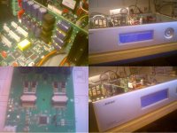
I've got some experience with the TAS5261 and build upto 10 boards with them. The results are quite good and come close to the specs in the datasheets. I've used an AP ATS2 to do the measurments. At this moment I'm thinking of designing a small module with PWM controller on board. So people can use this as a module to work with. Maybe this can be interesting for someone on this forum?
Hello Sproggit,
The pictures are from the first test board. On the board are 2 TAS5261's with a PWM controller TAS5021 (I didn't want to make a software prototype just hardware). It's adapted to work in a Bose audio managment system but only to test the principle. Currently I'm working out a stand alone version. But I'm not quite sure how complete it's going to be (DSP on it or not, and what inputs to put on it). Maybe you can give me some input on that.
Kind regards,
Stefan
Attachments
- Status
- This old topic is closed. If you want to reopen this topic, contact a moderator using the "Report Post" button.
- Home
- Amplifiers
- Class D
- Texas Instruments TAS5261