Hi Tony,
Well, 1st attempt failed. I had the dc current scale of my ammeter set at 250mA and it swings all the way to full scale (I think its very much over) when I turn the power on. I just had to change it to 2.5A scale. While I am waiting for the caps to discharge to 4.7k breeders, I turn it back to 250mA scale every now and then. It still deflects to full scale even at +-ve rail voltages of about 20V. I will desolder Q7 and check if it is still working and change P1 to 5k (it was stated as 2.2k in the original article). Hopefully it can give me something better.
One more thing : when we are using the current limiting resistors. If just one of them get blown, then current is still passing thru the other side, Could it damage the ccomponents like that? Could we use this method while setting the bias? I guest that the wattage of the resistor will have to be 5W to tolerate a current of 220mA, right?
that is indicative of blown part(s), you have to be patient in rooting out defective parts, even momentary powering up can cause busted parts.....
in my case i test my boards with full voltage, i use 10ohm 1/2 watt resistors soldered unto busted fuses one for each rail...this is in order to protect output devices from shorting out...
one thing, your bias circuit is very, very important as a wrong parts placement there could fry your output devices..
that is why the 10ohm 1/2 resitors are output trannie life savers....
Well, 2nd attempt failed, bond fire this time!
This time, I check the output transistors first (on the output board) and the main board is tested again as before with 20mV of dc offset. I tested Q7 and change P1 to 10k set at about 3k for start. 2 33ohm 1/2W in parallel for protection for each rail, supposed to substain a current of ~240mA. As soon as I throw the power switch, the 4 resistors burst into flames.
If the main board is having a dc offset of 20mV as in the test, should it be assumed that its working fine expect the vbe part (but I had test Q7 too ). Any suggestion now?
I am a bit suspicious about the connection to D1-D4. If it is not connected well, could the circuit behave like mine? I am also worried about the JKL MNQ connections too. These are places where things might go wrong. I will try to check them this afternoon.
Apart from these, I am getting a bit confused with the grounding of it too. Mr Leach explicitly mentioned that we should grounded to central for 2 connection from the main board : 1 near the input and 1 at the output. But if the ground at the input is ground to central, then what is R51 doing there. Would it be useless like that kind of connection. I remember I read something about this R51 in some article but I could never find that again.
As soon as I throw the power switch, the 4 resistors burst into flames.
You really have some serious problems, a normal working amp will not do that.
so if you can have somebody go over your work and check everything, sometimes a fresh mind can see something you might have missed..
from where is sit, you have your bias circuit problems..an open circuit like bias diodes not connected correctly will cause instant burnout of the resistors..
we can tackle the offset and grounding issues once your amp does not fry resistors anymore..
this problem also happened to me several times, just be patient, maybe take a day off to refresh...whatever you do don't rush, be deliberate...
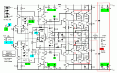
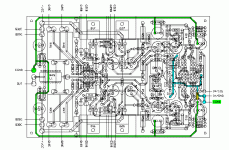
I have made 2 boards for this, one is the main board, slightly modification of Mr. Leach's original, the other one is the output board, with all the output trannies on it, together with some other components in the vincinity. The distribution of the components are shown as in Post #10. The 2 boards are connected thru +-ve rails, output, Ground and 6 wires marked as JKL NMQ. Hope I am describing it clearly.
diode string marked A' , B' should all be in series, and connected to A , B on the main boad, make sure you got them right, as any mistake here has serious consequences, P1 should be set to maximum resitance, for the least amount of bias, Q7 check that orientation is correct.
from my experience, any mistake here will fry your resitors...
in my case in one of my amps, i got the orientation of Q12,22 and Q23,13 wrong becuase i used a to92p transistors then...
from my experience, any mistake here will fry your resitors...
in my case in one of my amps, i got the orientation of Q12,22 and Q23,13 wrong becuase i used a to92p transistors then...
Hi Tony,
I think I got it right this time. It is the diodes that's causing the trouble. This time I use another connector and everything semms to be OK now. The dc voltage is still at 20mV and bias currnet adjust to about 100mA. So comes the next question, the grounding.
In the attached schematic, I had the signal ground painted in blue and central ground in green. So are the traces on the board. In Mr. Leach's construction (or board test) manual, he said about connecting the central ground at the input (which looks the same as the signal ground) also. If it is connected like that, what will be the significance of R51 (painted in yellow) then?
Attachments
So comes the next question, the grounding.
congratulations!! patience is always rewarded......
the recomendation given by dr. leach was based on ground plane boards... here is howi do my grounding.
1. locate a point in your chassis for a central ground point, i used a 4mm screw here and round lugs.
2. the center-tap lead of the main power transformer goes to this bolt first.
3. one each of the psu caps's positive and negative leads goes in next on top of the one in 2.
4. the ground return of the speaker terminals goes on top of 3.
5. one ground wire for each board goes on top of 4. (speaker ground)
6. the signal input, with a sheilded wire goes to the input jacks, the ground side of the jacks are earthed thru a 4.7~10 ohm 1/2 watt resistors one end of which is tied directly to chassis at input jack side, a smaller grounding wire is also needed to go to the central ground point in the drawing you marked green..
this should complete your earthing..
please go over the pictures i posted to see what i mean..
you may replace your fuses now with regular ones..
enjoy....
what will be the significance of R51 (painted in yellow) then?
you may omit it...
- Status
- This old topic is closed. If you want to reopen this topic, contact a moderator using the "Report Post" button.
- Home
- Amplifiers
- Solid State
- testing super leach without a scope

