Finish all the ebce padding for the metal cans with 2 extra jumpers added.
To djk :
According to this page :
http://users.ece.gatech.edu/~mleach/lowtim/part2.html
If we get thru the procedure as stated, the testing of the borads was done without the output to-3's. or it's because of my terrible understanding power that I mis-interept the procedure? Procedure 1 under "Testing the Circuit Boards" seems to be 'bypassing ' the outputs, isn't it? So, should the outputs be there or not when testing the circuit board? Can't afford the scope so keep trying to dig a way to do it with the DVM.
"Temporarily tack solder two 100 ohm resistors to the back of each circuit board, one from the loudspeaker output to one side of R36 and the other from the loudspeaker output to the other side of R36."
Could not be more clear. There is no reference to the output TO3 transistors in this section.
"installing the 4 power transistors" is later in the destruction manual under the heading "Installing the Power Transistors".
The balance of the testing procedure requires a scope.
HTH
Could not be more clear. There is no reference to the output TO3 transistors in this section.
"installing the 4 power transistors" is later in the destruction manual under the heading "Installing the Power Transistors".
The balance of the testing procedure requires a scope.
HTH
Borrow a scope and follow the instructions (for the SuperLeach):
"Testing the Circuit Boards
After you solder the parts to the circuit board, it is tested using the same procedure specified for the Low TIM circuit board. First, you must solder the short circuit jumper across Q7 and you must solder the 100 ohm 1/4 W resistors from the loudspeaker output to the emitters of Q16 and Q17. If you don't have a bench power supply that puts out plus and minus 85 to 93 V dc, you can test the circuit board at a lower voltage. I would prefer test voltages of at least plus and minus 50 V dc. An option is to connect bench power supplies in series to obtain the plus and minus 85 to 93 V dc. I have routinely connected two 40 V Hewlett Packard power supplies in series with the positive and negative outputs of a Hewlett Packard 50 V dual power supply, and I have never had any problems. To protect the circuit boards, you might want to put a 100 ohm 1/4 W resistor in series with the plus and minus power supply leads for the tests. The current drawn by the circuit should be low enough so that the voltage drop across these resistors is less than 1 V if nothing is wrong on the circuit board. There are 2 ground wires from the circuit board. Both must be connected when testing the boards.
I can't stress how important it is to be careful in testing a circuit board. Even simple errors can cause the loss of many expensive transistors. I always use current limited bench power supplies to test a circuit board before and after connecting the power transistors. I also bias an amplifier using current limited power supplies in place of the amplifier power supply. When I initially power up an amplifier with its own power supply, I always use a Variac variable transformer to slowly increase the ac input voltage from 0 to 120 V rms while observing the amplifier output on an oscilloscope with a sine wave input signal. If I see anything wrong on the oscilloscope, I turn the Variac to zero and try to diagnose the problem using the bench power supply. I never use a load on the amplifier for these tests."
With every thing connected (as yours is) you could power it up through a lightbulb to limit the current in the event of a fault. On 120V mains a 75W bulb is about right, I have no idea what would be right for 240V.
djk said:With every thing connected (as yours is) you could power it up through a lightbulb to limit the current in the event of a fault. On 120V mains a 75W bulb is about right, I have no idea what would be right for 240V.
We used to use a 100 Watt bulb in series for our 220 Volt power supply.
")
i'm working on the following attenuator for general testing, using the sound card line input and suitable software (like Audio Test Bench) as an oscilloscope...... one thing i forgot was an ac/dc coupled input switch.
the same circuit can also be used as an output attenuator for the sound card output.
the same circuit can also be used as an output attenuator for the sound card output.
Attachments
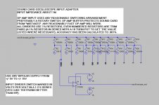
I don't have a circuit to post but the switched bypass/cut Pi attenuator will serve you better.
I have twelve DPDT switches and it achieves 0db to -61.05db in 0.05db steps.
It is 600r Zin and Zout.
I have loaded the output with a fixed 600r so that it attenuates correctly when feeding a high Zin and that shows Rs=300r for any receiving amp. Selected 1% resistors achieves very good accuracy.
I have twelve DPDT switches and it achieves 0db to -61.05db in 0.05db steps.
It is 600r Zin and Zout.
I have loaded the output with a fixed 600r so that it attenuates correctly when feeding a high Zin and that shows Rs=300r for any receiving amp. Selected 1% resistors achieves very good accuracy.
hi,
there is another way, use 10ohm 0.5w resistors in place of the rail fuses. i have tested all my leach amps this way.
set the 5kohm bias trimpot to maximum, and ensure that bias diodes are not reversed...
i lost many resistors this way, but i have yet to lose a power transistor...
good luck...
there is another way, use 10ohm 0.5w resistors in place of the rail fuses. i have tested all my leach amps this way.
set the 5kohm bias trimpot to maximum, and ensure that bias diodes are not reversed...
i lost many resistors this way, but i have yet to lose a power transistor...
good luck...
Tks Tony,
I think I get the way you mentioned. :
1. The only thing we can measure is the biasing current, right? (measure the voltage across the dispendable reistor and calculate the current, right?)
2. Then I'll let it burn in (say for 10 -20 min) without a signal. If it gets hot, then there could be some parasitic oxcillation and I should try to find the source.
3. Then measure the DC voltage at the output (< 50mV) and find the source of trouble if there is any.
4. Connect a dumny load to the output and feed a signal (a music source?) and wait for it to blow up for 10-20min.
5. If not, then connect the speaker and find distortion with your ears.
That's the procedure I had in mind. Anyghing more than or supplement to that?
BTW, were you initailly located at Phillipines before?
yes, biasing current is set to about 250mA, but in my case, i set it to about 120mA...works fine for me...but you have to measure it mwhen the heatsink is warmed up.
once you have verified that it is not frying resistors, and that offset voltage is below +/-100mV, then you have a working amp...
i am in manila at present, i have holiday till feb24...
as long as the biasing points are as per circuit, you should have no problem with this amp.
once you have verified that it is not frying resistors, and that offset voltage is below +/-100mV, then you have a working amp...
i am in manila at present, i have holiday till feb24...
as long as the biasing points are as per circuit, you should have no problem with this amp.
leach output bias current
Leach suggests about 40 to 45mA per output pair.
The Cordell thread has settled on Vre=15mV to 25mV.
I use 0r337 for Re and when set to Vre=24mV the bias current per pair is about 71mA and 213mA for the 3pair output stage.
Leach generally uses a higher value for Re and this results in a lower requirement for optimum bias.
That sounds too high.Tony said:yes, biasing current is set to about 250mA, but in my case, i set it to about 120mA
Leach suggests about 40 to 45mA per output pair.
The Cordell thread has settled on Vre=15mV to 25mV.
I use 0r337 for Re and when set to Vre=24mV the bias current per pair is about 71mA and 213mA for the 3pair output stage.
Leach generally uses a higher value for Re and this results in a lower requirement for optimum bias.
That sounds too high.
Andrew,
That is what was written on the 1980 article published in the Audio magazine, in page 56, third paragraph on the right hand side...
I thought that was high too so I set my bias at 120mA and still got good results...
i can post the page here if the mods would allow it.
Tks Tony for going thru all the details. The photos aren't that good, are they? I don't know how to make good use of the digital camera. That is the best I can do with it.
In the meantime, the to-3s are made by mospec. I brought it about 3 years ago from ampslab. I had done an ETI-466 with some of it. Everything seems to be OK. I am just doing a test with it for the super-leach. If the pcbs (concentration is on the output board, where as the main board is just modification on Leach's ) is OK, I would make 2 with ON's MJ21193/94 for I have a handful of them lying around. BTW, how muscular would the toroid has to be? I use a 700VA (which I use for testing ) for testing single channel but I think I need a 1KVA for a stereo superleach, don't I? And I think my heatsink 5"x10"x2" is not good enough for natural convection neither. I am still looking for a bigger one and any suggestion for that?
After finishing this, I will go back to the 10xTO-247 version that I had left lying around for a while. That board is modified to 2 seperated boards too whereas the original one is about 10" x4" double sided.
Tks for the tip again.
rolandong said:hi tony,
do you still got some pairs of your .3R barbados emitter resistors for outputs ?
roland
i do...but i am not letting them go....i have future plans for them...
but i do have 470ufd/16v bipolar electros, i can spare you a pair if you like. also, i have incoming caps. 47000uf/100v nichicon electros rated at 105*C.
- Status
- This old topic is closed. If you want to reopen this topic, contact a moderator using the "Report Post" button.
- Home
- Amplifiers
- Solid State
- testing super leach without a scope