Eric,
maybe you use 3M "Quick-Circuit" (which is self-adhesive copperfoil) and glue it on the floor below the carpet and make a slit in the carpet at the backside of your speakers, high WAF, she won't notice any more cable (until she gets curious "where has this durned cable disapppeared", [devilish") ] then i wont sit caught in your skin)
] then i wont sit caught in your skin)
Steve,
I would prefer to run them separately, widely separated as the field diminishes in strength (the field of the +conductor is not meant to penetrate the edge of the -conductor and vice-versa (remember, it ideally should find zero distance to penetrate?). But in this case i would do everything to prevent the conductor from moving relatively to the other conductor. PP-based adhesive tape is fine here. Or use adhesive copper foil. Or double sided adhesive tape.
If you have to keep them close, stack them firmly and, again, keep them from moving against each other in either direction. In this case the +conductor's filed faces the "zero" thickness of the minus conductor i.e. as soon as it has dig into the other conductor, it "falls out" at the opposite side.
I am not that deep into cable theory .. the reasons i use twisted pairs are that
#1
one wire is ground and shields the other
#2
both wires pick up the same common mode signal in differential use
#3
they do not fall apart
At one short listening test i slightly preferred air spaced wire pairs to twisted ones.
After all you cannot avoid fields to mix up by definition fields have infinite reach (with infinte decay, of course )
Originally posted by mrfeedback
I have seen and heard flat foil cable like you describe and I liked the sound, but ergonomically not such good WAF compared to 25 pair.
maybe you use 3M "Quick-Circuit" (which is self-adhesive copperfoil) and glue it on the floor below the carpet and make a slit in the carpet at the backside of your speakers, high WAF, she won't notice any more cable (until she gets curious "where has this durned cable disapppeared", [devilish
] then i wont sit caught in your skin)Steve,
Originally posted by Apogee
If I switch to foil conductors, is it better to "stack" them on top of each other with an insulator between for each polarity or run them separately.
I would prefer to run them separately, widely separated as the field diminishes in strength (the field of the +conductor is not meant to penetrate the edge of the -conductor and vice-versa (remember, it ideally should find zero distance to penetrate?). But in this case i would do everything to prevent the conductor from moving relatively to the other conductor. PP-based adhesive tape is fine here. Or use adhesive copper foil. Or double sided adhesive tape.
If you have to keep them close, stack them firmly and, again, keep them from moving against each other in either direction. In this case the +conductor's filed faces the "zero" thickness of the minus conductor i.e. as soon as it has dig into the other conductor, it "falls out" at the opposite side.
I ask this question because of how often I've read about twisted conductors sounding better... I've never understood exactly why since it results in a longer path to the destination...yet everyone seems to do it...
I am not that deep into cable theory .. the reasons i use twisted pairs are that
#1
one wire is ground and shields the other
#2
both wires pick up the same common mode signal in differential use
#3
they do not fall apart
At one short listening test i slightly preferred air spaced wire pairs to twisted ones.
If as you mention, the field surrounding the conductor is affecting the signal, then is it better mix the fields or isolate them?
After all you cannot avoid fields to mix up by definition fields have infinite reach (with infinte decay, of course
)Twisting reduces self-inductance, as the field reverses with each twist.
As for TDR measurements, did some years ago on some crap sold here known as Music Ribbon.
Basically, a paralle pair of wires is somewher between 100-150 ohms, or so. If you start paralleling pairs (Bob Pease would agree on this one), you cut the impedance in half every time you double the number of pairs. So with a 32-conductor cable, you could get down near 10 ohms. Don't remember the exact value, but it was close to that.
I agree with the tiny conductor school-of-thought, but my intuition leads me to think flat conductors need some help in the way of geometry to sound right.
But I could be all wrong..........
Jocko
Hello All,
Yep, it is called the blind leading the blind .originally posted by SsZERO I think a lot of people who get too carried away with audio equipment begin to make things up in order to propogate their interests. It also creates business opportunities for companies and individuals alike.
originally posted by Bernard [I/]Thankyou Bernard, (also for your sense of humour) very good idea, but I have wooden floor and very expensive Persian carpet squares - I think she who does the vacuum cleaning might notice !maybe you use 3M "Quick-Circuit" (which is self-adhesive copperfoil) and glue it on the floor below the carpet and make a slit in the carpet at the backside of your speakers, high WAF, she won't notice any more cable (until she gets curious "where has this durned cable disapppeared", [devilish ] then i wont sit caught in your skin)
BTW - do you have periodic advertised Persian carpet company super special emergency final liquidation sales in your neck of the woods ?
I totally agree that any such conductors need to be locked against the motor action caused by conducted currents and, yes this is quite critical.
#1 - not correct according to my theory lessonsI am not that deep into cable theory .. the reasons i use twisted pairs are
#1 that one wire is ground and shields the other
#2 both wires pick up the same common mode signal in differential use
#3 they do not fall apart
At one short listening test i slightly preferred air spaced wire pairs to twisted ones.
#2 - yes, provided that load impedences on both conductors are equal
#3 - yes, high WAF when vacuuming especially.
Air spaced - Extended listening on seriously good stuff ( Aleph 0 and Accuton etc ) I don't agree.
Yes, Einstein described "Spooky action at a distance" and Tesla described action infinitely fast over infinite distance without loss !.After all you cannot avoid fields to mix up by definition fields have infinite reach (with infinte decay, of course )
Suck what ?originally posted by Jocko Homo Twisting reduces self-inductance, as the field reverses with each twist.
The theory books I read (and have read) say that with a (multiple) closely twisted pair the send and return current opposing fields cancel precisely and this gives the property of low loop inductance, also low external fields pickup.
Also, please consider that our standard telephone street distribution cable systems would not work with such good crosstalk figures if this were not so !
This is applied physics, not belief systems, yeah ?originally posted by Jocko Homo but my intuition
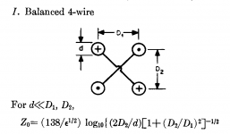
Back to the theory books - characteristic impedence is ratio of conductor diameters to separation distance - old knowlege - not bagging you, just correcting you. Consider the existance of 300 ohms aerial cable.originally posted by Jocko HomoBasically, a parallel pair of wires is somewhere between 100-150 ohms, or so.
To repeat, can some one please send Jocko Homo some samples for TDR testing quick before he makes more gaffes like these !
My bed is calling, good night all,
Regards, Eric.
more gaffes?
100 to 150ohms is a good estimate for most two conducter pair wire. Il Duce of the TDR does not "Gaffe" when it comes to wire impedence very often! (Never?..... well hardly ever.) 300 ohm twin
lead is not typical of a pair of wires as the distance between wires is much greater than the wire diameter.
H.H.
I wasn't refering to "twin-lead". Thank you, Harry.
And I wasn't talking about multiple twisted pairs either. Just twisted pairs, in general. Someone asked why, and I answered.
And how much telephone cable have you measured?
As for the Persian rug theory......I have a close friend whose family is a big player in that market.
Persians tell a lie??????? If they only tell 5 a day, they consider it a slow day.
Anything else you wanted to know?
Jocko
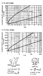
Hope the diagram is readable. Best I could do with a borrowed scanner, and the 100k limit.
It is from the Reference Data for Radio Engineers, out of print for about 5 years.
I have a whole lot more equations/ diagrams for the next time you tweak me. [joke]
Like this one..........
It is from the Reference Data for Radio Engineers, out of print for about 5 years.
I have a whole lot more equations/ diagrams for the next time you tweak me. [joke]
Like this one..........
Attachments
First, thanks to all for their help!!!
Ok, now I'm confused about the foil. It seems that there are two different opinions on the "correct" way to run the cables to the speakers - separate vs together... In either case, it seems that the key is minimizing the physical interaction between the two - either by keeping them far enough apart so the fields don't "touch" each other or by mechanically attaching them so they can't move... Is there any real advantage to either way? (I realize that I'm opening a can of worms here...)
What about wrapping the foil in a spirial (similar to twisted pair) over an inert medium such as teflon? Would it then tend to act more like a coaxial cable from an impedance standpoint?
Thoughts???? Has anybody tried it???
Thx,
Steve
Jocko's TDR Testing.
Hello All, Thankyou Jocko for your cable characteristic impedence calculation diagrams.
Jocko, what test setup do you use for TDR testing - Can it be economically home built ?
Also, in your library of measurements have you examined Canare star quad speaker cable ?
Has anybody sent you some 10, 20, or 25 pair yet ?
If so, I'm sure we that we would all be interested in your measurement results.
Regards, Eric.
Hello All, Thankyou Jocko for your cable characteristic impedence calculation diagrams.
Sorry to accuse you of gaffe, but it was late, I was tired, and you did not state conductor diameters or spacing.Basically, a parallel pair of wires is somewhere between 100-150 ohms, or so.
Jocko, what test setup do you use for TDR testing - Can it be economically home built ?
Also, in your library of measurements have you examined Canare star quad speaker cable ?
Has anybody sent you some 10, 20, or 25 pair yet ?
If so, I'm sure we that we would all be interested in your measurement results.
Regards, Eric.
My TDR is some ancient unit built by H-P.
I have some Canare star-quad interconnect only. In use in one of my systems.
You can build a rudimentary unit to give you some idea. I bet Harry is an expert at that, as he has done lots of work on digital cables.
All you need is a step-generator (or square wave), and a good 'scope. The main advantage to an expensive unit is that you can better resolve minor pertubations, and at smaller intervals.
Keep the cables short: the longer they are, the more likely the reflection will be attentuated, and you will not get as accurate results.
If you messs with one long enough, you soon realise why 1 meter for digital cables is a real bad idea.
Remember, it is a TIME DOMAIN measurement.
No more hints. Two in one day is enough. [joke]
Jocko
Found 2 star-quad types around here to measure.
#1 is about 0.3" OD, blue jacket, so I suppose it is something Audioquest made at one time. Looks like 16 Ga. conductors.
#2 is by FMS, about 3/8" OD. Fatter, hollow-core (or "flux gate", as Alex liked to say) conductors of probably the same effective gauge. Should have lower impedance due to closer spacing.
#1: z=45 ohms
#2: z=33 ohms
Remember z=sqrt(L/C), so I'm not sure I would use a cable that reaches the mythical "8 ohm" range. Too much C could cause some amps to smoke.
Ciao......Jocko
Since I'm stuck here at the shop waiting on someone to bring over their CD player so I can RIP OUT THE SAA7220/TDA1541AR1 AND REPLACE THEM WITH '1704s.......measured another cable.
Cable #3, a variation of the star-quad setup. Something Alex at FMS called "MicroWave". Imagine a twisted pair cable, made up of "flux gate" conductors. Make an identical one, and twist those 2 cables together to make one. Should measure like 2 twisted pairs in parallel. And it does: 58 ohms.
Jocko
Cable #3, a variation of the star-quad setup. Something Alex at FMS called "MicroWave". Imagine a twisted pair cable, made up of "flux gate" conductors. Make an identical one, and twist those 2 cables together to make one. Should measure like 2 twisted pairs in parallel. And it does: 58 ohms.
Jocko
Hello Jocko, Thankyou for your replies.
Ok, so a quick google search (cable tdr testing) turned up these articles -
http://www.thom-tech.com/TDR.HTM
http://www.qsl.net/n9zia/wireless/appendixF.html
http://www.engineering.usu.edu/ece/faculty/furse/TUTORIAL/TDR/sld001.htm
http://www.hut.fi/Misc/Electronics/circuits/tdr.html
Ok, I now more clearly understand why digital cable should NOT be 1M length.
Question - Given that DACs despite output filtering still emit RF junk, then DAC to AMP connections really ought to be via a transmission line (coax ?) correctly driven and correctly teminated?
Also for all other line level interconnections ?
Has any body tried this correctly ?
Why should balanced lines (do they) work any better ?
Thanks for posting these measurements.
I agree that low (8 ohm or so) impedence cable is not desirable because of high shunt capacitance - what about an amplifier purpose designed to drive high capacitance loads ?
Question - Star quad (30-40 ohms or so) should provide a better speaker line and matching at least at HF where drivers impedence(uncompensated) rises to these sorts of values ?
Regards, Eric.
Sorry if too many questions, just interested.
High frequency TDR
Since Time Domain Reflectrometry deals with frequencies too high for even a cane toad to hear, why the the interest in TDR for a cable carrying audio frequencies. They invented something called a zobel network to adress this issue of stability driving capacitive cables.
H.H.
Since Time Domain Reflectrometry deals with frequencies too high for even a cane toad to hear, why the the interest in TDR for a cable carrying audio frequencies. They invented something called a zobel network to adress this issue of stability driving capacitive cables.
H.H.
Attachments

Uh Oh, my third post and I'm jumping in the middle of this <groan>
Just honestly wondering - are you doing a TDR on the cable or on the junction at the end of the cable?
To be really accurate, you'd have to connect the cable to a speaker. But then are you reflecting off the speaker wiring or the cable wiring, or the interconnect, or ....
Anyway.......for those of you making TDRs: do not use a resistive splitter. A BNC "Tee" works fine.
Just honestly wondering - are you doing a TDR on the cable or on the junction at the end of the cable?
To be really accurate, you'd have to connect the cable to a speaker. But then are you reflecting off the speaker wiring or the cable wiring, or the interconnect, or ....
- Status
- This old topic is closed. If you want to reopen this topic, contact a moderator using the "Report Post" button.
- Home
- Loudspeakers
- Multi-Way
- Telephone cable speaker wire