Hi,
if the transformer is sensibly designed
If You use a small SMPS instead it certainly is no issue.
Besides the SMPS supplies for a quite constant voltage and allows for a lower dc running into the onboard regulator, thereby reducing heat power considerably.
The PSRR of the circuit takes care of any residual that might possibly be left.
They are not all idiots who design a single casing device with the transformer inside and not all tweaks stand up to the claimed improvements.
Real improvements can be had, if the speed regulating feedback loop is checked and tuned on demand.
And it certainly makes sense to check and replace old lytics and to check and maintain the mechnics.
Also tuning the original Technics Tonearm or replacing it alltogether with a superior arm can make a noteable difference.
All else is more for guts feeling than of true influence on sonics.
jauu
Calvin
if the transformer is sensibly designed
will be no issue.it will still vibrate
If You use a small SMPS instead it certainly is no issue.
Besides the SMPS supplies for a quite constant voltage and allows for a lower dc running into the onboard regulator, thereby reducing heat power considerably.
The PSRR of the circuit takes care of any residual that might possibly be left.
They are not all idiots who design a single casing device with the transformer inside and not all tweaks stand up to the claimed improvements.
Real improvements can be had, if the speed regulating feedback loop is checked and tuned on demand.
And it certainly makes sense to check and replace old lytics and to check and maintain the mechnics.
Also tuning the original Technics Tonearm or replacing it alltogether with a superior arm can make a noteable difference.
All else is more for guts feeling than of true influence on sonics.
jauu
Calvin
1. We plan to sell it with all the holes drilled. We can provide it without holes, with the holes like I made for this project or with different holes. I expect that we'll need to move things a bit for the 110/220 V version since the circuit board is larger. Like I showed earlier, the one I made has space for one of Pete's circuit boards that can be used just for the rectifier. If you don't want that, we can make the case a little smaller.
2. Yes, we can provide the mounting plate. We can make it just like the one I used, or we can make different holes - however you need it.
2. Yes, we can provide the mounting plate. We can make it just like the one I used, or we can make different holes - however you need it.
Our intent is to make a "kit" that's fairly easy to assemble with readily available parts. I was hoping to get a little feedback on what sort of options people would like to have or what parts they'd like to use to build something like this.
I suppose I should list the parts used for the external chassis - I'll try to do that this evening. We can also vary the holes for other switches, lights and connectors.
I suppose I should list the parts used for the external chassis - I'll try to do that this evening. We can also vary the holes for other switches, lights and connectors.
Sounds good. Are prices known for everything?
Case with holes, without holes, etc.
Yes. I'm not sure if it's okay to list any of that here since this isn't a commercial thread, so feel free to PM me.
A kit would be a great idea.
Regarding the size of the holes for switches and connectors, I think it would be nice to leave that an option.
From the photo's I saw from your case, I would like to use a different on/off switch and connector. Was think about a mini-XLR type connector.
As for a light a simple LED would be ok, red but not one of those very bright ones but one that's dimmed. Doable with a resistor in line (iirc) or a LED that is already less bright.
I think those exist, but really not sure anymore.
I'll PM you. But please keep in mind I'm not ready to order just yet.
Money helps to fund this, and it's been a money expensive period for me...
")
Hi,
just because of interest.
Is there an explanation why there´s a current compensated choke behind the regulator and not in front of it?
As it is one of the most prominent aims to get a as low and constant regulator output impedance over a as wide bandwidth as possible, the position of the choke seems a bit odd on first glance.
It spoils regulation.
Even if the differential mode impedance is lower over most of the bandwidth, the stray inductance (not specified here) will give a rising impedance response.
As the copper resistance is low a high Q tank circuit may be formed together with the following capacitance.
If that happensthe idea of the regulator is caricatured.
jauu
Calvin
Okay, since I'm using this regulator in a different application that it was originally designed for, I checked with Pete regarding your questions. There is no risk of forming a tank circuit and no harm in using the choke at all. Though there is probably little benefit in using it either. It's intent is to help filter any high frequency noise that's generated by the load - as I understand. So, it would be just fine to save a few bucks and omit it. If you have another design that you prefer, you could always build it onto the board instead. Though I like Pete's design and it works really well.
I would certainly try it for a while without the power conditioner then see if you can tell a difference with it. If you already have one for your other electronics, it would be an interesting "experiment" to report on. I think it would be hard to justify a significant investment in one hoping for more improvement. IMHO.
I'm in the process of doing the PS mod so that's why I asked about the power conditioner. I already have one I'm not using at the moment so once I get the PS mod/tone arm rewire/repaint done I'll give it a try.
One effective way to gauge whether something makes a change is to put it in use for a week or two. Then remove it from the system and listen again. If things sound the same, the "new thing" didn't change anything. If things sound different, then you have to determine "good" different or "bad" different.
One effective way to gauge whether something makes a change is to put it in use for a week or two. Then remove it from the system and listen again. If things sound the same, the "new thing" didn't change anything. If things sound different, then you have to determine "good" different or "bad" different.
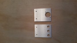
Finally a little down-time to get more info posted. I've had a few guys asking about the brackets so my apologies for the delay.
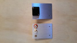
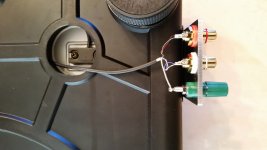
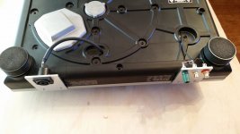
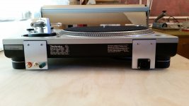
Below are some pictures of the external brackets we made for RCA and power connectors. Obviously, these are handy if you want detachable cords - I for one prefer not dragging along something to trip over.

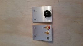
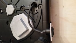
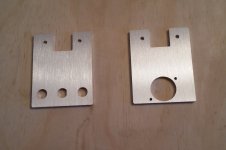
The power connector used here is the Neutrik NL4MP, same as the one I used on the power supply chassis. RCA's are Cardas CTFA in a 0.375 inch dia hole. - fairly common. The third hole shown in the RCA bracket is for an insulated ground post. I didn't want to ground to the outside of the chassis through the bracket and through the internal chassis ground as well, hence the insulated post.
The signal wire coming out is Cardas shielded tonearm wire, it's just the shielded version of what I rewired the arm with.
You can see where the ground post is on one side of the RCA's. I've changed that and put it between the two RCA jacks. With it in the middle, the shield wire can be used as a "strain relief" for the 33 awg signal wires - seems like a better idea.
Below are some pictures of the external brackets we made for RCA and power connectors. Obviously, these are handy if you want detachable cords - I for one prefer not dragging along something to trip over.
The power connector used here is the Neutrik NL4MP, same as the one I used on the power supply chassis. RCA's are Cardas CTFA in a 0.375 inch dia hole. - fairly common. The third hole shown in the RCA bracket is for an insulated ground post. I didn't want to ground to the outside of the chassis through the bracket and through the internal chassis ground as well, hence the insulated post.
The signal wire coming out is Cardas shielded tonearm wire, it's just the shielded version of what I rewired the arm with.
You can see where the ground post is on one side of the RCA's. I've changed that and put it between the two RCA jacks. With it in the middle, the shield wire can be used as a "strain relief" for the 33 awg signal wires - seems like a better idea.
Attachments
- Status
- This old topic is closed. If you want to reopen this topic, contact a moderator using the "Report Post" button.
- Home
- Source & Line
- Analogue Source
- Technics SL1200 internal brackets, regulator and external power supply