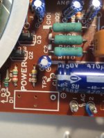
The schematic for SL-1200 and for the Sp-25 are basically the same, refer to post 15, with the exception of the SL-1200 shows a 1,000uf 50v rather than a 470uf 50v for the filter. Go on line and pull up the service manual for your particular SL-1200 model, and it will give you a schematic, and other good stuff. As far as I can tell the transformer is the same for the two models.
I tried the external power supply mod on an AT-LP240. I like the table semi-stock with the preamp and switch board removed and tonearm wires run directly to the RCAs, so I had high hopes for the external PS. It was quite a bit different than the one described for the Techincs. The transformer has two windings, one center tapped that is rectified to +/- 30VDC, and another winding that is rectified to 20VDC. I moved the transformer to an external enclosure and added large banks of capacitors, but I'm not sure I like the results. I'm not done fiddling with it, though. I also have a Technics SL-1500 that I plan to mod for comparison.
Follow up on my AT mod. I made a couple of changes to the external PS and fixed a cold solder joint. Now my AT-LP240 sounds very open and dynamic with much improved inner detail. Much improved over the stock internal power supply. Thanks for your original post, 6L6!
Received my SP-25, and it does appear it is basically the same as a SL-1200, at least electrically. Removed the transformer and built a CRCR power supply, unfortunately I didn’t check the secondary A.C. which turns out to 37.5 vac and it took out one of my 3300uf 50 volt caps. So replaced them with some 100v caps with lesser UF values, my house voltage is 120vac, which is probably higher than the unit was originally designed for. So if making this modification I would recommend 63 volt caps at a minimum. Currently output with the CRCCRC filter with 17.5 ohms resistance and 3.6k bleeder getting an output of 49.5 volts. Will see what it loads down to when I get the TT back together, as it is currently disassembled for painting. I think it is fortunate that I decided to remove and remote the P.S. as I don’t think the 470UF 50v cap install on the original board would have survived for long. Thanks to 6L6 and others for the post on this modification.
You guys really inspired me with this thread! I've got 3 of Technics 1200 with KAB regulators inside that I want to convert to external PS and I had a few questions:
Would something like this power supply (one shared supply) work well to power my 1200s? Your thoughts on this, please:
You Can DIY!: An Ecological Power Supply for Power Amplifiers
This can be set to any output voltage and it's regulated, build for power amps. Seems like this is even easier than building 3 separate supplies with the original transformers and adding rectifiers and pre-regulators three times.
thanks,
Herman
Hi,
used the MW PM-05 and PM-10 for my SL5210 and other Technics based players as supplies.
No issues at all so far ... they just do their job.
Besides, the main discrete regulator is not the only regulator stage of the electronics.
Apart from the actual coil driver IC all other ICs feature additional supply regulating stages, among these are RC-filtering, Z-Diodes and discrete Regulators.
jauu
Calvin
I would like to ask for help connecting the new Meanwell power supply in place of the stock transformer:
Do I connect the AC input to where the blue wires went?
Do I connect the DC output to the regulator, bypassing the rectifier on the main board?
Do I need to put a ferrite filter in line on the DC outputs?
thanks,
Herman
Do I connect the AC input to where the blue wires went?
Do I connect the DC output to the regulator, bypassing the rectifier on the main board?
Do I need to put a ferrite filter in line on the DC outputs?
thanks,
Herman
Hi,
almost all SMPS require additional filtering to fulfill the EMI regulations and the DS of the manufacturers regularly suggest components and values.
At least the input should therefore run through a filter.
At the output it depends on what comes next.
If there´s a good regulator in close proximity to the SMPS output one might not need output filtering.
Still tough filtering the output reduces ripple and EMI considerably before entering the regulator stages.
For a highly sensitive analog circuit like a phono stage, I´d say post filtering is a must .... for the motor supply I´m not so sure if it´s worth for more than just a good feeling in the guts.
Anyway, as the components are compact in size and don´t cost much, I´d add them to the list.
jauu
Calvin
Looking at the datasheet, block diagram, the EMI filter is built-in
www.meanwell-web.com/content/files/pdfs/productPdfs/MW/PM-10/PM-10-spec.pdf
www.meanwell-web.com/content/files/pdfs/productPdfs/MW/PM-10/PM-10-spec.pdf
Pass DIY Addict
Joined 2000
Paid Member
I would recommend experimenting with ANY SMPS before you spend the time and effort to refit the original transformer. While I am sure there are some that are good (somewhere?), MANY emit all kinds of EMI/RFI garbage, both through their wires and through the air (think AM transmitters). Plug the power supply in, attach a load, then hold it by your cartridge and see if it creates any interference.
Technics 1200 power supply update (using Ortofon OM20 MM cart)
Tried the Meanwell PM-10-24.
It needs a Ferrite ring on the outputs due to noise. No noise with two wraps around the ferrite ring).
It also benefits from a filter on the inputs (slight noise reduction), however the effect is less pronounced than using the output filter, which I feel is mandatory.
The PM-10-24 seems to give less torque for start up and braking of the platter. I will try the PM-15-24 for 15 watts of power. Perhaps the regulator needs to get 28v and that causes the loss of torque?
Last edited:
Another year later i am diggin out this old thread again. First i wanted to build an external PSU, but after calculating and thinking it over my interest switched to an internal mounted smps.
I had to order stuff anyway, so i added a Meanwell RS-15-24 to my basket. As it arrived i realised that the housed RS model should be connected to mains earth via its FG connector.
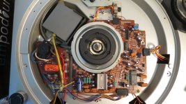
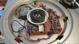
I opened my deck anyway to check if the size of the RS-Model SMPS would fit into the internal chassis of my technics 1200. I realised that my technics is pretty old, it has a darkbrown PCB.
I removed the Transformator and the PSU board, fitted the SMPS into the chassis, connected the old mains cable to the input terminals of the SMPS, connected the switch to the positive output terminal and wired the rest up.
I did not use the FG earth terminal for anything, and maybe this is the cause of my problem: everything is acceptable quiet until i touch the cartridge to put the needle on the record. Touching the cartridge produces a big amount of hum.
So my question is: would it make sense to switch to a power cable with N,P and FG? The Turntable would be the only device in my listening chain that would be connected to mains earth. Is this a good idea or stupid as hell?
I had to order stuff anyway, so i added a Meanwell RS-15-24 to my basket. As it arrived i realised that the housed RS model should be connected to mains earth via its FG connector.
I opened my deck anyway to check if the size of the RS-Model SMPS would fit into the internal chassis of my technics 1200. I realised that my technics is pretty old, it has a darkbrown PCB.
I removed the Transformator and the PSU board, fitted the SMPS into the chassis, connected the old mains cable to the input terminals of the SMPS, connected the switch to the positive output terminal and wired the rest up.
I did not use the FG earth terminal for anything, and maybe this is the cause of my problem: everything is acceptable quiet until i touch the cartridge to put the needle on the record. Touching the cartridge produces a big amount of hum.
So my question is: would it make sense to switch to a power cable with N,P and FG? The Turntable would be the only device in my listening chain that would be connected to mains earth. Is this a good idea or stupid as hell?
some pics of Meanwell SMPS integration inside Technics 1200
I am back with some pics of the modding.
During my first test after modding with my nagaoka mm cart i had a big amount of hum when i touched the cartridge or the headshell.
Now i switched to my Denon DL-110 which behaves dead quiet now") No Hum and no signs of With the old transformer built inside the technics 1200 i had massive problems with mechanical vibrations. If i had put the needle on the resting, non-rotating record groove, my DL-110 picked up the mechanical vibrations at around 50Hz caused by the transformer. I could even hear the transformer humming when i put my ears next to the platter while the turntable was turned on.
No Hum and no signs of With the old transformer built inside the technics 1200 i had massive problems with mechanical vibrations. If i had put the needle on the resting, non-rotating record groove, my DL-110 picked up the mechanical vibrations at around 50Hz caused by the transformer. I could even hear the transformer humming when i put my ears next to the platter while the turntable was turned on.
I was never aware of that nasty humming before i used my new DL-110 together with a dead-quiet diy preamp. It never bothered me back in my low-fi days using DJ-mixer and ortofon concorde carts..
The SMPS-Mod solved this kind of mechanical hum-problem, maybe i will optimise it with line filters or an added LM317 voltage regulator. But after trying the smps only, without any added filters, it does its job pretty well. Thanks Calvin for the hint
I am back with some pics of the modding.
During my first test after modding with my nagaoka mm cart i had a big amount of hum when i touched the cartridge or the headshell.
Now i switched to my Denon DL-110 which behaves dead quiet now
No Hum and no signs of With the old transformer built inside the technics 1200 i had massive problems with mechanical vibrations. If i had put the needle on the resting, non-rotating record groove, my DL-110 picked up the mechanical vibrations at around 50Hz caused by the transformer. I could even hear the transformer humming when i put my ears next to the platter while the turntable was turned on. I was never aware of that nasty humming before i used my new DL-110 together with a dead-quiet diy preamp. It never bothered me back in my low-fi days using DJ-mixer and ortofon concorde carts..
The SMPS-Mod solved this kind of mechanical hum-problem, maybe i will optimise it with line filters or an added LM317 voltage regulator. But after trying the smps only, without any added filters, it does its job pretty well. Thanks Calvin for the hint
Attachments
The SMPS-Mod solved this kind of mechanical hum-problem, maybe i will optimise it with line filters or an added LM317 voltage regulator. But after trying the smps only, without any added filters, it does its job pretty well. Thanks Calvin for the hint
Why not use the SMPS as the sole power supply: an NES-25-24 Meanwell SMPS can be adjusted down to 21.6 volts. This should be usable to bypass the complete internal power supply of the SL1200.
I liked Calvins contributions about leaving the internal regulators in the main board alone and let them do the job. SMPS should be run at around 70% of load. The RS-15-24 has way enough power (rated at 0.65 A output current) to run the technics without any readjustment. I am using no additional parts right now, but might add an HF filter cap at the output.
And i most likely will try and change the mains cable for a three-pronged one to connect to safety ground / mains earth.
And i most likely will try and change the mains cable for a three-pronged one to connect to safety ground / mains earth.
next step: make use of the original PSU PCB ..
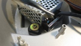
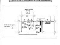
After testing the raw setup i am thinking about moving the power pcb back to its place inside the case for the reason of the original function of the power switch. I got myself the service manual for the technics 1200 to check out the original implementation of the power switch (attachment one)
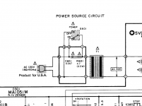
I tried to figure out, which position of the switch stands for on and off. I found the answer in another part of the manual (attachment two).
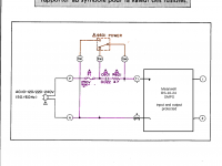
After that i tried to figure out how to wire everything to keept the power pcb as connecting board between mains AC, the mains fuse F1, power switch and SMPS. That new version is attachment three (sorry for the very ugly photoshop job) and i would be grateful if someone would take a look to see if my idea seems to be good or stupid. I am interested in your opinions..
After testing the raw setup i am thinking about moving the power pcb back to its place inside the case for the reason of the original function of the power switch. I got myself the service manual for the technics 1200 to check out the original implementation of the power switch (attachment one)
I tried to figure out, which position of the switch stands for on and off. I found the answer in another part of the manual (attachment two).
After that i tried to figure out how to wire everything to keept the power pcb as connecting board between mains AC, the mains fuse F1, power switch and SMPS. That new version is attachment three (sorry for the very ugly photoshop job) and i would be grateful if someone would take a look to see if my idea seems to be good or stupid. I am interested in your opinions..
Attachments
- Home
- Source & Line
- Analogue Source
- Technics SL-1200 DC Power Supply