hi , i am very sorry if there is misunderstanding; the feedback string in my amp is:
22k, 1k and 22 uF electro, with the positive facing the chip.
And it is based from many examples found on the web, maybe itis not correct, this schematic was adapted from the one i found at Soundwesthost , ESP or Elliot Sound Products web.Mr Elliot uses that, so i made the last one that way too. I must say that all my previous clones were made without a cap, just the 22k-1k resistors and they sounded very good; also i am about finishing another amp with the Fbk string values as recomended by Mr Daniel W from this forums that is 100k-2.7k-220uF but still have to finish it and test.
the feedback string in my amp is:
22k, 1k and 22 uF electro, with the positive facing the chip.
QUOTE]
Thanks for clarifying this point martin, in reference to dr frost scheme i follow the electro caps polarity as per below.
Attachments
There's that 22uF again.
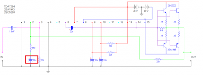
The passive input filter using 1uF and 22k gives a turn-over frequency (F-3dB) of ~7.2Hz
The NFB using 680r and 22uF has F-3dB of ~10.6Hz.
The input filter should be raised to >=15Hz, or the NFB filter reduced to <=4Hz
If you don't get a suitable ratio between the input filter and the NFB then the NFB capacitor will have significant AC voltage across it. That is not good for amplifier performance and not good for sound quality.
yes, any transistors and mosfet's IF YOU USE THE DESIGN POSTED A FEW PAGES BACK!!!, if you blow your mosfet's then that's ALL on you.
But again for Minion, yes the 3281/1302 should work just fine, and quite powerful transistors i might add, as always you just need to play with the 6.8ohm if it sounds bad
But again for Minion, yes the 3281/1302 should work just fine, and quite powerful transistors i might add, as always you just need to play with the 6.8ohm if it sounds bad
Just acquired a 10" 500W RMS Subwoofer so hopefully ill show a video with a Bridged 7293 (5200/1943) blasting it to the max")
Congrats...I'm excited to watch that video....
Sound great!!
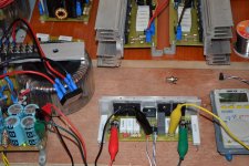
Tested and working LM3886 + 2 pair 5200/1943 Power transistor.... Rail supply +/-38VDC offset is 0.8mV and bias reading is 482mV on 10R/10W resistor at +/- rail, the amp is dead silent and no power on thump......
@ dr frost and Martin, please advise what need to change to increase bias on 10R/10W resistor.
Regards,
Attachments
Last edited:
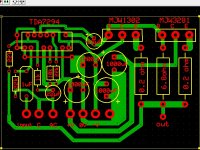
Hi wiljj78, i´m glad you made this, i´ll try to make your pcb after i finish a parallel p2p almost done it; i don´t quite understand your question. That .8mV offset is the dc at the output?, and where is the 10r 10W res located? Must say i am no expert, there´s alot of people more educated in electronics in this thread, hope someone can answer that.But still don´t get to know exactly what you ask.
Sorry! watching your pic, i see the big resistors by the power inputs? How do you connect them and then what, measure across them? Then you measure V drop across those, at iddle? then have to calculate amps: E=IR this: 48mA, but then again
somebody with more knowledge should calrify.
It sounds great? ithink it does, really mine did even better without the crap pre and eq integrated at the speakers input! Remember drfrost said we should fiddle with the 6.8 ohm Sync resistor and listen what we could get. Congratulations!
martin martinnez
uruapan michoacan
Hello Martin and Sorry if i didn't elaborate my message clearly because it's kinda late already in my place when i try post my message....
10R/10W resistor have used instead of light bulb tester when powering up the amp for the first time and Yes i'm getting .8mV dc offset at +/-38VDC rail supply.
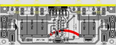
10R/10W resistor is connected under the board instead of fuse on my first power, and measuring voltage across 10W resistor I’m getting 482mV on + rail and 556mV on –rail at iddle, I must say that this is the 2nd way how i get my output bias reading in my other amps (aside from the primary way of course by measuring the voltage across output emitter resistor).
Also I notice on heat sink temp. (Behind the IC portion) was getting warm a lot quicker when i crank up the volume compare to the power output transistor portion.
I'm really curious how to increase the bias on the output transistor in this typology at lease by achieving 1.5V per rail across 10W resistor.
Anyway I’ll try to play around the sync resistor as dr frost said and will update the result.
Thanks for your quick response Martin, really appreciated...
Regards,
That .8mV offset is the dc at the output?, and where is the 10r 10W res located?
10R/10W resistor have used instead of light bulb tester when powering up the amp for the first time and Yes i'm getting .8mV dc offset at +/-38VDC rail supply.
Sorry! watching your pic, i see the big resistors by the power inputs? How do you connect them and then what, measure across them? Then you measure V drop across those, at iddle? then have to calculate amps: E=IR this: 48mA, but then again
somebody with more knowledge should calrify.
It sounds great? ithink it does, really mine did even better without the crap pre and eq integrated at the speakers input! Remember drfrost said we should fiddle with the 6.8 ohm Sync resistor and listen what we could get. Congratulations!
martin martinnez
uruapan michoacan
10R/10W resistor is connected under the board instead of fuse on my first power, and measuring voltage across 10W resistor I’m getting 482mV on + rail and 556mV on –rail at iddle, I must say that this is the 2nd way how i get my output bias reading in my other amps (aside from the primary way of course by measuring the voltage across output emitter resistor).
Also I notice on heat sink temp. (Behind the IC portion) was getting warm a lot quicker when i crank up the volume compare to the power output transistor portion.
I'm really curious how to increase the bias on the output transistor in this typology at lease by achieving 1.5V per rail across 10W resistor.
Anyway I’ll try to play around the sync resistor as dr frost said and will update the result.
Thanks for your quick response Martin, really appreciated...
Regards,
Last edited:
Tested and working LM3886 + 2 pair 5200/1943 Power transistor.... Rail supply +/-38VDC offset is 0.8mV and bias reading is 482mV on 10R/10W resistor at +/- rail, the amp is dead silent and no power on thump......
@ dr frost and Martin, please advise what need to change to increase bias on 10R/10W resistor.
Regards,
Amazing! Just what i needed, i was seacrching for someone to try out, you did so, thats impressive!
How much output power do you get?
Amazing! Just what i needed, i was seacrching for someone to try out, you did so, thats impressive!
How much output power do you get?
Thanks Mihkus... i still need more measurement to get more details about the amp capability as it was very late (1:45am) last night when i power up the amp for the first time. but my first impression have noticed was it got more power to deliver my speaker than then normal LM3886 amp. and like Martin said on his previous post that the amp is not that boomy but it's punchy...
Tonight will try to carryout more test.
Regards,
Hey wiljj78! How is your amp going, ihave here my clone with 22k-1k-47uf fback string, ready to use with 5200-1943 transistors, have you measured yours?
I just need to make a better wiring and fit my PS to start testing, did you
try different resistors?
Hope everything gets OK.
martin martinez
uruapan michoacan
I just need to make a better wiring and fit my PS to start testing, did you
try different resistors?
Hope everything gets OK.
martin martinez
uruapan michoacan
How can this schematic (7293 one) be modified to be used for sole purpose as a subwoofer amp? are there any modifications that can be made to make it great for lows sacrificing the highs?
i am thinking of a Frankenstein high capacitance supply and low pass filter, but apart from that...WHAT IN THIS CIRCUIT?
i am thinking of a Frankenstein high capacitance supply and low pass filter, but apart from that...WHAT IN THIS CIRCUIT?
Simple yet powerful configuration, i like it a lot dr frost, but can the output stage be used in open loop chip amps like the old TA7240 which has no link between output and input? also can both the amp and the output stage biased at two different voltages? Thanks in advance.
How can this schematic (7293 one) be modified to be used for sole purpose as a subwoofer amp? are there any modifications that can be made to make it great for lows sacrificing the highs?
i am thinking of a Frankenstein high capacitance supply and low pass filter, but apart from that...WHAT IN THIS CIRCUIT?
Maybe you could make the whole amp into an active low-pass filter.
- Home
- Amplifiers
- Chip Amps
- TDA7294 + Power Transistors AMP (TDA7293 to come also)