Indeed, I thought put 2 push-pull output for 8 ohms and 4 or 5 push-pull of 4 ohms.
What do you think of the complementary pair 2SA2151/2SC6011, that's heavy?
Well looking at the SOA alone they offer more power then the 1943/5200, i think ill give them a try also for the new TDA7293 im making.
EDIT: But can see that they are more expensive and harder to come by for me.
Last edited:
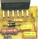
this is what i used
Hi there, first , to say thanks for the replys about local caps for my amp; and this is some guide as to how i made it : the schem comes from soundwesthost, or elliot sound products. I just modified it a little to use it with dr frost´s schem, and made it using this: Mick Feuerbacher Audio Projects
as a guide to make it point to point. I just didnot use the local PS decoupling caps but now i´m gonna fit some small ones, maybe 220Uf
like Mr Rod Elliot does in his gainclone. The res and cap that are not connected in the schem were put at th spkr output, as a hi freq filter, or zobel network.
from there is the same schem as dr frost amp take the fb res to the output,
the chip out to the bases and res node, and that is it. It sounds very good by itself, and i think that i dont like it so much with the integrated pre and eq, still have to find some time to improve it. Also did not experiment with different sync resistors, but next one i will.Please excuse me for not having posted before, but i was away and a bit too much distracted with the job.
Anyway i plan to make some more of this and will be posting as soon as posible. Thanks and hope this helps somebody.
Martin Martinnez
Uruapan , Michoacan, Mex.
Attachments
You should use at least 470 μF for the decoupling capacitors, instead of 220 uF.
Below is a direct quote from the LM3886 datasheet, from the last paragraph of the "Supply Bypassing" section, on Page 19:
"If adequate bypassing is not provided the current in the
supply leads which is a rectified component of the load
current may be fed back into internal circuitry. This signal
causes low distortion at high frequencies requiring that the
supplies be bypassed at the package terminals with an
electrolytic capacitor of 470 μF or more."
Hi there, first , to say thanks for the replys about local caps for my amp; and this is some guide as to how i made it : the schem comes from soundwesthost, or elliot sound products. I just modified it a little to use it with dr frost´s schem, and made it using this: Mick Feuerbacher Audio Projects
as a guide to make it point to point. I just didnot use the local PS decoupling caps but now i´m gonna fit some small ones, maybe 220Uf
like Mr Rod Elliot does in his gainclone. The res and cap that are not connected in the schem were put at th spkr output, as a hi freq filter, or zobel network.
from there is the same schem as dr frost amp take the fb res to the output,
the chip out to the bases and res node, and that is it. It sounds very good by itself, and i think that i dont like it so much with the integrated pre and eq, still have to find some time to improve it. Also did not experiment with different sync resistors, but next one i will.Please excuse me for not having posted before, but i was away and a bit too much distracted with the job.
Anyway i plan to make some more of this and will be posting as soon as posible. Thanks and hope this helps somebody.
Martin Martinnez
Uruapan , Michoacan, Mex.
Thanks for sharing your LM3886 schem Martin and of coarse for TDA7294/3 from dr frost, Thank you very much guys or sharing this intresting and powerful chipamp.
@ martin just to clarify if the above schem is now ready to adopt the output stage using 5200/1943?
Caps clarification
Hi Martin,
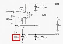
Just a quick clarification, below 22uf cap with red mark in your schematic is a Metallized polyester film or electrolytic? in dr frost scheme it shows electrolytic, Please clarify.....
Thanks and regards,
Hi Martin,
Just a quick clarification, below 22uf cap with red mark in your schematic is a Metallized polyester film or electrolytic? in dr frost scheme it shows electrolytic, Please clarify.....
Thanks and regards,
Attachments
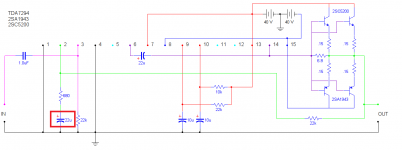
Hi Wiljj78! Its an electro, and yes this 3886 clone is being used with a 5200/1943 pair, and it´s good! In my first make, i did not use it, went with the 1k res to ground, and it is OK, the second has it but havent tested yet, I´m planing to try different sync resistors with this one. Will post as soon as posible.
ttan98 : yes it´s working with 3886 and 5200/1943.
By the way , i like the low frequency response of the simple 22k-1k fbstring, it is not boomy and has good punch, like said before, i think it sounds better by itself than with the integrated pre and eq.
ttan98 : yes it´s working with 3886 and 5200/1943.
By the way , i like the low frequency response of the simple 22k-1k fbstring, it is not boomy and has good punch, like said before, i think it sounds better by itself than with the integrated pre and eq.
Hi Wiljj78! Its an electro, and yes this 3886 clone is being used with a 5200/1943 pair, and it´s good! In my first make, i did not use it, went with the 1k res to ground, and it is OK, the second has it but havent tested yet, I´m planing to try different sync resistors with this one. Will post as soon as posible.
ttan98 : yes it´s working with 3886 and 5200/1943.
By the way , i like the low frequency response of the simple 22k-1k fbstring, it is not boomy and has good punch, like said before, i think it sounds better by itself than with the integrated pre and eq.
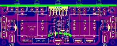
Thanks Martin.... trying to make the PCB for for my next project and glad to hear your inputs if there's any error on the PCB.
Regards,
Attachments
Hi,
I must admit I have not read through all the postings there, my initial query is that will TDA7294 and Toshiba o/p transistors work with other chipamps like LM1875, 3886, 3875?
I suspect so, if yes has the any of these combos been tested yet.
Thanks for your time.
Or look at this one, with LME49830 and lateral mosfets:
http://www.diyaudio.com/forums/soli...amplifier-based-lme49830-lateral-mosfets.html
The whole concept is pretty broadly applicable:
Here are some application notes that have circuits that can boost the output voltage and/or current of any monolithic voltage amplifier, such as an opamp or chipamp:
AN-272 at http://www.ti.com/lit/an/snoa600b/snoa600b.pdf
AN18 at http://cds.linear.com/docs/en/application-note/an18f.pdf
Cheers,
Tom Gootee
Last edited:
Or look at this one, with LME49830 and lateral mosfets:
http://www.diyaudio.com/forums/soli...amplifier-based-lme49830-lateral-mosfets.html
The whole concept is pretty broadly applicable:
Here are some application notes that have circuits that can boost the output voltage and/or current of any monolithic voltage amplifier, such as an opamp or chipamp:
AN-272 at http://www.ti.com/lit/an/snoa600b/snoa600b.pdf
AN18 at http://cds.linear.com/docs/en/application-note/an18f.pdf
Cheers,
Tom Gootee
What can I say, a very thorough response thanks.
Thanks Martin.... trying to make the PCB for for my next project and glad to hear your inputs if there's any error on the PCB.
Regards,
The coupling capacitor if I see it well is 220nF. It is too low.
With the 22k resistor it gives -3dB at 32Hz filter.
Ppl say it should be below -3dB at 2Hz, so you need at least least 3.6uF cap there. Like a usual 4.7uF one. (I use 2.2uF that gives 3.2Hz)
The coupling capacitor if I see it well is 220nF. It is too low.
With the 22k resistor it gives -3dB at 32Hz filter.
Ppl say it should be below -3dB at 2Hz, so you need at least least 3.6uF cap there. Like a usual 4.7uF one. (I use 2.2uF that gives 3.2Hz)
Hello mrWagner,
Thanks for your comments... in ference of the very good sounding amps from yorkville LM3886 Amps of APEX, the input coupling capacitor was used is 220nf wima, in this case if the amp will not perform well as it should be using this 220nf then will make a multi hole on PCB in order to use 5-22.5mm pitch of 4.7uf-10uf wima, let me know you thoughts.
Attachments
The 22uF is usually an electrolytic.Hi Martin,
Just a quick clarification, below 22uf cap with red mark in your schematic is a Metallized polyester film or electrolytic? in dr frost scheme it shows electrolytic, Please clarify.....
Thanks and regards,
It normally sees a very small DC voltage and a very Small AC voltage.
If it is sized correctly these two voltages are so small that it does not affect the audio performance of the amplifier.
But @ 22uF this converts the amplifier into a high pass filter. That changes the way the voltages get applied to this capacitor.
Make that capacitor ~5 to 10times larger if you want good bass performance from your amplifier.
The input filters should determine the pass band of the amplifier, not the internal filtering of the amplifier.
Last edited:
yorkville LM3886 Amps of APEX, the input coupling capacitor was used is 220nf wima
And they use 100k res instead of your 22k as I see, so they get 7Hz at -3DB.
You should check how bit the 4.7uF caps are, as they get bigger and bigger quite fast.
About the 22uF cap. I also use a 22uF one and as you can see it is quite huge on the left of the chip (lm3875). But it is not electrolytic. AndrewT is that a problem there?
Last edited:
"as you can see", no I can't see.
Yes 22uF causes a problem if it chamges the amplifier into a high pass filter.
The High Pass Filter should be at the Input.
The amp should be capable of handling all the signal that gets through the passive input filtering.
Just as I explained in my earlier post.
Yes 22uF causes a problem if it chamges the amplifier into a high pass filter.
The High Pass Filter should be at the Input.
The amp should be capable of handling all the signal that gets through the passive input filtering.
Just as I explained in my earlier post.
The 22uF is usually an electrolytic.
It normally sees a very small DC voltage and a very Small AC voltage.
If it is sized correctly these two voltages are so small that it does not affect the audio performance of the amplifier.
But @ 22uF this converts the amplifier into a high pass filter. That changes the way the voltages get applied to this capacitor.
Make that capacitor ~5 to 10times larger if you want good bass performance from your amplifier.
The input filters should determine the pass band of the amplifier, not the internal filtering of the amplifier.
That's very good information... Big thanks Andrew your inputs is always valuable for me...
And they use 100k res instead of your 22k as I see, so they get 7Hz at -3DB.
You should check how bit the 4.7uF caps are, as they get bigger and bigger quite fast.
About the 22uF cap. I also use a 22uF one and as you can see it is quite huge on the left of the chip (lm3875). But it is not electrolytic.
Thanks for the helpful tips mrWagner, i noted that and will change mine to 4.7uf coupling input caps.
"as you can see", no I can't see.
That rather big red thing what I ment.
It is that big, so it is not the high pass filter. The bigger, the lower the pass goes. I guess that is why many ppl use there electro caps as the foils are way too big.
Hello,
I tried to route a TDA7293 with 2SA2151/2SC6011, what do you think?
Free - Envoyez vos documents
Free - Envoyez vos documents
Regards
I tried to route a TDA7293 with 2SA2151/2SC6011, what do you think?
Free - Envoyez vos documents
Free - Envoyez vos documents
Regards
- Home
- Amplifiers
- Chip Amps
- TDA7294 + Power Transistors AMP (TDA7293 to come also)