sorry for off topic but i dont have PW option.
X.G.
X.G. do You have maybe source files pcb for LM from this post
http://www.diyaudio.com/forums/show...4230#post384230
X.G.
X.G. do You have maybe source files pcb for LM from this post
http://www.diyaudio.com/forums/show...4230#post384230
Khm. About explosions, white smoke and other stuff related to TDA´s strange behaveour with separate PS for driver and output stage.vuki said:I tried to isolate TDA7293's driver supplies with 12R & 100uF and the IC exploded very nice immediately after power up
First off all driver stage must have same or greater rail voltage then one on output stage and must be first to receive voltage on power up.
Did someone in dtasheet spoted two diodes that connect driver and output stage voltage rails?
Diodes are there to prevent delayed voltge rise on driver stage.
Thanks for your time.
Do you guys know how to compute the Power dissipation of the TDA729x chip family. The datasheet mentions Pd < 50W in the absolute ratings section. And I can't find any formula to compute it.
One thing to point out too is that to improve effective PSRR, the positive rail supply ripple should be perfectly symmetrical to the negative rail supply ripple.
Meeting these conditions will make the chip extremely quiet with very good SNR.
Do not supply STBY and Mute pins from Vs. Use separate 5V logic instead.
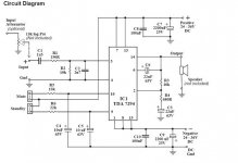
This schematic is ****.
The 2n7 cap on the input, depending of the input impedance (high Z) it will become a 6Db/oct low pass xover.
Furthermore, the bypass caps (100nF) must be as close as possible to the chip, and have one for EACH pin, to prevent oscillations. In the schematic you tie them all togeter and have only one cap.
It will work fine or not, depending of the environment, the power supply, and the input impedance, but who designed this don't have much knowledge.
Bootstrap capacitor really needed
I build a 3-way amplifier with the TDA7294V. It works fine with 30V on the power rails and 37V on the preamp rails. But now I wonder if I should add the bootstrap or not. Looking at the schematic the zenerdiode keeps the voltage between the bootstrap pin and the speaker at 15V. So I'm considering the following options:
1) Keep the bootstrap cap to stabilize this 15V voltage
2) Leave it out
3 Connect the bootstrap pin to the power rail.
Has anybody looked at this? What would be the best?
-_nando-_ said:This schematic is ****.
The 2n7 cap on the input, depending of the input impedance (high Z) it will become a 6Db/oct low pass xover.
Furthermore, the bypass caps (100nF) must be as close as possible to the chip, and have one for EACH pin, to prevent oscillations. In the schematic you tie them all togeter and have only one cap.
It will work fine or not, depending of the environment, the power supply, and the input impedance, but who designed this don't have much knowledge.
Im sorry nando, i just taking this schematic from kitsrus.com and try build them, yes sounds like more bass, but its works so far, but the input sens looks like very low.. any suggestion from you will appreciate...
but some suggestion like this:
The gain is
1+R3/R4 which is approx 16 times, or 24dB. If you
wish to increase the input sensitivity you may
change the resistors to suit. Changing R3 to 22k
would increase the gain to 30dB and lower the input
required for 50W into 8Ù, to 0.6V, without affecting
performance too much.


Hi,
I made BPA using 7293's, blew it 2 times previously, now fixed and working fine.
Can anybondy help on how to use high efficiency circuit(like Class H) shown in Datasheet, if i parallel 3+3 (BPA App). The current required for total 6 Chips would be rather high.
Moreover could somebody help using Mosfets to switch the rails.
Regards,
Criss.
Hi,
I made BPA using 7293's, blew it 2 times previously, now fixed and working fine.
Can anybondy help on how to use high efficiency circuit(like Class H) shown in Datasheet, if i parallel 3+3 (BPA App). The current required for total 6 Chips would be rather high.
Moreover could somebody help using Mosfets to switch the rails.
Regards,
Criss.
Knock:: Knock:: Anybody Intrested

I experimented with the TDA7293 today, it always played for 30 ~ 35 seconds then distorted while the sound disappeared and a buzz in the speakers appears. Turn it off and on again then I got the same thing, the IC was warm although it did not work for a long time. Suddenly I decided to move the connection of the bootstrap 22uF capacitor from pin 12 to the output, it played with the same sick symptoms then exploded  I did not fully read the datasheets indeed, what I wished was a clear application circuit for this IC that works, if it is available on some body's PC, please upload it here, coz I ended reading this thread seeking for a schematic that ran without problems, also explanations are appreciated on how to correctly handle mute and stand-by functions.
I built the circuit as in the datasheets, but I connected mute and stand-by pins to Vs+, I looked at the datasheets, max voltage rating was not mentioned, so I assumed Vs+ is allowed. I don't know if the IC is a fake one, or I did a mistake concerning the 30 seconds behavior I will buy from a different vendor and use +5 Volts for the mute and stand-by as well as that circuit in figure 5 of the datasheets. PSU limits were not exceeded any way. If there are other things to watch, please advise.
I did not fully read the datasheets indeed, what I wished was a clear application circuit for this IC that works, if it is available on some body's PC, please upload it here, coz I ended reading this thread seeking for a schematic that ran without problems, also explanations are appreciated on how to correctly handle mute and stand-by functions.I built the circuit as in the datasheets, but I connected mute and stand-by pins to Vs+, I looked at the datasheets, max voltage rating was not mentioned, so I assumed Vs+ is allowed. I don't know if the IC is a fake one, or I did a mistake concerning the 30 seconds behavior
I will buy from a different vendor and use +5 Volts for the mute and stand-by as well as that circuit in figure 5 of the datasheets. PSU limits were not exceeded any way. If there are other things to watch, please advise.I forgot to mention that I had the distorted output with TDA1514 14 years ago! It was fake, and being so dumb, I kept buying the same IC from the same vendor for 6 times thinking I done a wrong
In the TDA7293 I did nothing wrong, tomorrow I will get 2 extra chips from a different vendor, hoping they are not fake too
In the TDA7293 I did nothing wrong, tomorrow I will get 2 extra chips from a different vendor, hoping they are not fake too
Ah, connect mute with a 10k resistor.
Connect standby with a 22k resistor and also make it charge a 10uF cap (time delay).
Most of the TDA7294 datasheet will operate the TDA7293's but the 2000uF power caps values are considerably too large--use 330uF's (or a nearby figure) as a starting point (in addition to a separate power supply board).
The pinouts are a bit different, but the design is the same.
Fake chips are a different product, unfortunately without a datasheet. One thing is for sure that they need decreased operating voltage (de-rating). And, they probably do need in+ to in- stabilizing cap (220pF) as well as output flyback diodes, output RC, and output inductor//resistor. In other words, the fake chips need "babied" (gentle treatment).
The fake chips are also prone to increased or varied DC offset, so making a parallel amplifier could be quite difficult (DC offset should be identical, preferably zero, for parallel operation).
The real chip is 4 ohm stable on a single chip, so no need for a parallel amplifier unless you're making parallel+bridge.
Last edited:
Ah, connect mute with a 10k resistor.
Connect standby with a 22k resistor and also make it charge a 10uF cap (time delay).
I did the cap part yesterday, also the voltage was half what TDA7293 can handle, and from my experience, I had the same situation with TDA, STK and LM chips. All fake chips I had behaved the same way:
Some of them work for few seconds, and then start distorting the output and then explode. Others will distort directly when powered on and explode
STK4221II, LM3886, TDA1514, TDA7293, OPA541 are those I had fake recently. Now I know the vendors who sell fake chips.I did the cap part yesterday, also the voltage was half what TDA7293 can handle, and from my experience, I had the same situation with TDA, STK and LM chips. All fake chips I had behaved the same way:
Some of them work for few seconds, and then start distorting the output and then explode. Others will distort directly when powered on and explode
The fake LM3886's and LM1875's have a tendency to do massive DC offset and then break because the load is too great. This can be stopped with an output cap (good dc protection for your workbench test speaker).
Unfortunately, the fake chips can break down after months of operation rather than immediately.
Yesterday I got a new TDA7293, it worked fine, but I was shocked by the details when heard songs, those highs details, I never heard on any other amplifier. Strange how detailed this IC is. Bass is not as strong as other ICs, OPA,LM and STK. In some songs too much detailed highs are not appreciated indeed. Afterall I did not like it that much, for me still the STK is a winner.
Yesterday I got a new TDA7293, it worked fine, but I was shocked by the details when heard songs, those highs details, I never heard on any other amplifier. Strange how detailed this IC is. Bass is not as strong as other ICs, OPA,LM and STK. In some songs too much detailed highs are not appreciated indeed. Afterall I did not like it that much, for me still the STK is a winner.
Increase the strength of the RC radio frequency blocker that goes at the input. Increase the strength of the RC that goes at the output. (decreases treble noise)
Decrease the feedback resistor value and compensate with the other (to ground) resistor. (subtracts the raspy)
Increase the input load (fixes the bass).
tda7293 separate power
hello, I read this thread from the beginning - thanks to all who explained the strange behavior of this Chip. However one question - maybe a stupid one - arises:
Did anybody try the simple idea of using an rc-network like maybe R = 47 Ohms series and C = 470 myF (to ground), between the main power and the primary stage power connections (that was the first idea here and the Chip blew up), but with a schottky-diode in parallel to the Resistor ? The Schottky-diode would limit the danger of the supply voltage in the primary stage being lower than in the power stage to about 0,4 Volts.
But as long as the voltage drop over R stays lower than 0,4 Volt (about 8 ma possible) we would keep some filtering of powersupply noise ? This will only work with a stiff powersupply for the main power, but it is worth a try.
Best regards from Hamburg
Martin
Hi guys!
Will I create an audio amplifier with TDA7293. I have (dispose) of 250VA transformer with the secondary of 2x27Vac the stereo version. Speakers with impedance of 4R. So please give me a scjematic (circuit) or project Amplifier with TDA 7293 for this power supply.
Thanks for your help!
Will I create an audio amplifier with TDA7293. I have (dispose) of 250VA transformer with the secondary of 2x27Vac the stereo version. Speakers with impedance of 4R. So please give me a scjematic (circuit) or project Amplifier with TDA 7293 for this power supply.
Thanks for your help!
Last edited:
- Status
- This old topic is closed. If you want to reopen this topic, contact a moderator using the "Report Post" button.
- Home
- Amplifiers
- Chip Amps
- Tda7293v