It sounds extremely strange that you would have any less bass with the separate PS arrangement. As for distortion in midrange, you do need some sort of film cap close to the IC - if you have to, move the electrolytic further out. Did you also remove the bootstrap cap?
Keep in mind that if you are comparing channels, feed them both the same MONO signal, so you don't end up comparing channels of the recording!")
Keep in mind that if you are comparing channels, feed them both the same MONO signal, so you don't end up comparing channels of the recording!
Let me tell you about that TDA7293V chips.
1st: they do sound pretty ok
2nd: they are extremly sensitive and tend to blow up easily. My application is the "high efficency" configuration or a so called class G amplifier. There is nothing wrong with the design itself. Extensive simulation was done and after a while I saw that there is no reason not to implement the design you find directly in the datasheet. It's done as it should be. My heatsink has 1.5K/W and at full power (90W) the amplifier run as it should - no problems at all. Power supply is +-20V regulated and +-35V non regulated.
As I mentioned, the IC is very sensitive. Here is what you should not do: never ever should the +-20V supply be activated before the +- 35V. This would damage the chip. Never ever short circuit the the +-20V power supply, I did it accidentaly while the chip was playing music - it blow up spectaculary. Never ever turn off muting if the stand-by is not turn off - death of IC happens after next power-up.
I never saw a TDA-series chip that could withstand any kind of abuse. Short circuits, power limiting, that is all a lie. I managed to burn one while driving a load at 100kHz for instance and almost none will survive a short circuit, no matter wether the signal is present or not. With a sturdy power supply they will blow like firecrakers regardles of the claimed protections. For other TDA chips withouth the mute function, let me say that minimizing powerup noises obviously does not mean what a normal human would think it means. If one of your supply rails fails the chip will blow. No mercy at all. The only way to deal with this TDAs is to get a working design, bolting it in to the chasis, glue the cables and just turning the whole unit off when doing anything with the output.
And that is just too bad. Altough sounding nice, this TDAs makes me want to work on a solid state design. By the way: I do have several working designs and I blown an incredible 6 chips (!) Mostly (half) due to stupidity and some due to their sensitivity. But keep in mind - I know what I am doing but I still manage to blow them once in a while. And that is just too bad. Just too sensitive.
Any chip amp will do similar things if precautions are not taken, so will solid state. I have not found the TDA729x series any better or worse in that regard. Especially fiddling with the output - most amps with short protection actually do not blow when a short is applied, but when it is removed, courtesy of wire inductance providing a nice peak way beyond what the semiconductor can withstand. BTW - DO NOT trust the internal TDA729x power line clamp diodes, put uour own 1N400x or 540x from output to power lines!
Not sure about your problems with power up and down, mine are completely silent both ways.
Not sure about your problems with power up and down, mine are completely silent both ways.
Hmmm, you should read the post carefully... for instance the on/off noises refer to TDA chips withouth the mute function. As far as the inductive spike: I accidentaly shorted the +-20 supply, not the output - no spike there. Those are my experiences. I hope it will help somebody.
Hi all
After having a little break I have made some little changes to my amp. I've changed the rectifier bridge with discrete schottky diodes(MUR420) - that change did give me almost nothing in terms of voltage drop - maybe some +-0.2V (+-40.2V). Then I've replaced the 470k resistors in regulator with 220k, as suggested by Ilimzn. After this change I have Vs around +-36V. Don't know, if 4V is enough for regulation...
And finally I've put 100nF caps on Vs pins, almost in parallel with 220mkF electrolytes - that was not easy...
Now I have a clear conscience for giving my TDA7294's clean power Seems like the slightly higher distortion in midrange has disappeared, but it is still present in both channels - I don't get, what's wrong, maybe other parts are limiting me? Probably listening to mp3(high bitrate) through external Sound blaster Live 24bit isn't the best idea, but for now I have no other source. I also use quite old Soviet era floorstanders "Amfiton 100AS-022" - maybe it's their fault
When listening, I made Winamp playing mono, but mono sounds really dull I also used HQSoftProc software resampling plug-in to resample to 48kHz.
There IS some difference between channels, but it may be because of not symmetrical placement of speakers in the room, one standing closer to the corner than the other.
Now I want to measure the distortion in both channels - at least to know, if I'm on the right way Is there any way to do it without an oscilloscope? (maybe RightMark? but couldn't even make it work to test loopback in my blaster...)
After having a little break I have made some little changes to my amp. I've changed the rectifier bridge with discrete schottky diodes(MUR420) - that change did give me almost nothing in terms of voltage drop - maybe some +-0.2V (+-40.2V). Then I've replaced the 470k resistors in regulator with 220k, as suggested by Ilimzn. After this change I have Vs around +-36V. Don't know, if 4V is enough for regulation...
And finally I've put 100nF caps on Vs pins, almost in parallel with 220mkF electrolytes - that was not easy...
Now I have a clear conscience for giving my TDA7294's clean power
Seems like the slightly higher distortion in midrange has disappeared, but it is still present in both channels - I don't get, what's wrong, maybe other parts are limiting me? Probably listening to mp3(high bitrate) through external Sound blaster Live 24bit isn't the best idea, but for now I have no other source. I also use quite old Soviet era floorstanders "Amfiton 100AS-022" - maybe it's their fault When listening, I made Winamp playing mono, but mono sounds really dull
I also used HQSoftProc software resampling plug-in to resample to 48kHz.There IS some difference between channels, but it may be because of not symmetrical placement of speakers in the room, one standing closer to the corner than the other.
Now I want to measure the distortion in both channels - at least to know, if I'm on the right way
Is there any way to do it without an oscilloscope? (maybe RightMark? but couldn't even make it work to test loopback in my blaster...)Doing this kind of critical listening with MP3s is not going to give you a valid impression at all - even for the highest bitrates. A proper speaker and amp will reveal MP3 instantly even at 320k, no matter what codec you used - mp3 is just NOT intended for this. Use a wav file or a CD, even through your setup, it will sound MUCH better than MP3 no matter how resampled it is. SB live may be a problem, though, due to it's internal 48k sampling rate. The internal resampler is not very good. But, you should be able to resample the wav file to 48k using your resampler program and then play it at 48k, to avoid the SBlive resampling algorithm.
Hi all!
Tried to measure THD and IMD with SpectraPLUS. To feed the output of the amplifier I made a simple resistive divider (100Ohm in series with output and 3.3Ohm between output and ground). Can anyone comment, if these are optimal values, or should I use som other?
The program is realy powerful, I liked it, but for now I still get inconsistent results - for instance one time I get 1.2% IMD, other time I get 0,65% IMD - all with the same levels set in Windows mixer(oh, I chenged small film caps near Vp 0,33mkF, 1mkF, 100nF and got the best IMD results with 0,33 unknown film between -Vp and ground and 100n between +Vp and ground (0,63% IMD) - odd combination ) In non-split unregulated channel I got ~0,83% IMD.
All with 60Hz and 1/4 x 7000Hz frequencies, 60Hz was -10dB.
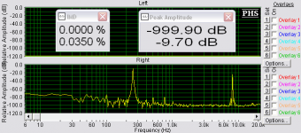
In other test with 250Hz and 1/4 x 8020Hz the results were MUCH better - ~0.035% in both channels.
THD in split Vs, Vp channel was 0,047% with test signal at 1KHz, -10dB level.
I've attached one of the plots -it can't be fully trusted, but maybe you'll have some comments or suggestions... I'm a newbie, and don't know much, how to interpret them
Tried to measure THD and IMD with SpectraPLUS. To feed the output of the amplifier I made a simple resistive divider (100Ohm in series with output and 3.3Ohm between output and ground). Can anyone comment, if these are optimal values, or should I use som other?
The program is realy powerful, I liked it, but for now I still get inconsistent results - for instance one time I get 1.2% IMD, other time I get 0,65% IMD - all with the same levels set in Windows mixer(oh, I chenged small film caps near Vp 0,33mkF, 1mkF, 100nF and got the best IMD results with 0,33 unknown film between -Vp and ground and 100n between +Vp and ground (0,63% IMD) - odd combination
) In non-split unregulated channel I got ~0,83% IMD. All with 60Hz and 1/4 x 7000Hz frequencies, 60Hz was -10dB.
In other test with 250Hz and 1/4 x 8020Hz the results were MUCH better - ~0.035% in both channels.
THD in split Vs, Vp channel was 0,047% with test signal at 1KHz, -10dB level.
I've attached one of the plots -it can't be fully trusted, but maybe you'll have some comments or suggestions... I'm a newbie, and don't know much, how to interpret them
Attachments
Now I've tracked the problem with inconsistent results - I've managed to connect both 3.3 Ohm and 100 Ohm resistors in series! in voltage divider 
After this was fixed I ran the tests again and got following results:
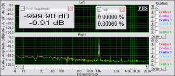
THD 1kHz, signal at -0.9dB:
Unreg. channel: 0.0146%
Split Vs, Vp : 0.0097%
Result: 1.5 times less distortion. Most obvious improvement here is much less higher order harmonics(from 3rd, and so on) in case of split supply. The second harmonic decreased a bit too.
IMD 60Hz, 7kHz, signal at -10dB:
Unreg. channel: 0.0963%
Split Vs, Vp : 0.0476%
Result: 2 times less intermodulation distortion
IMD 250Hz, 8020Hz, signal at -10dB:
Unreg. channel: 0.0146%
Split Vs, Vp : 0.0141%
Result: roughly the same intermodulation distortion, but comparing the graphs, the one of split suppy channel looked smoother.
THD graph of unreg channel:
After this was fixed I ran the tests again and got following results:
THD 1kHz, signal at -0.9dB:
Unreg. channel: 0.0146%
Split Vs, Vp : 0.0097%
Result: 1.5 times less distortion. Most obvious improvement here is much less higher order harmonics(from 3rd, and so on) in case of split supply. The second harmonic decreased a bit too.
IMD 60Hz, 7kHz, signal at -10dB:
Unreg. channel: 0.0963%
Split Vs, Vp : 0.0476%
Result: 2 times less intermodulation distortion
IMD 250Hz, 8020Hz, signal at -10dB:
Unreg. channel: 0.0146%
Split Vs, Vp : 0.0141%
Result: roughly the same intermodulation distortion, but comparing the graphs, the one of split suppy channel looked smoother.
THD graph of unreg channel:
Attachments

All these tests were taken at quite low total amp power, because the voltage divider didn't lower output voltage too much. 3.3 Ohm resistor didn't even get hot... however music is already listenable at this volume.
THD graph of split supply channel:
THD graph of split supply channel:
Attachments
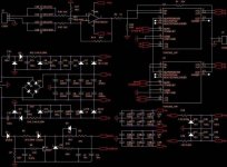
TDA7293 with separate supplies in parallel
Hello folks, first i want to thank you for usefull information you share. I figured out to make working amplifier with separate supplies, it works perfectly. the difference is audible with TDA7293 and TDA7294 chips. BTW the TDA7294 sounds better than TDA7293 and it gives higher slew rate.
My problem is that i blew up two of these chips immediately when i tried to make it parallel. I attached exact schematic i made. Please, help me to figure out how to make it work with separate supplies in parallel.
Thanx
Alex
Attachments
Hi, Alex!
Pleased to see here some folks from Lithuania
I didn't try to run TDA's in parallel, but from my experience with running on separate supplies, the chips still don't like turn-on/turn-off cycles(or it was becoming somehow unstable when the source - sound card was powered off ), and in a few months I've fried two chips. That was enough for me to stop experiment with dual supplies Resoldering a chip is a real pain
P.S. maybe someone has a good PCB design(or a link, where to get one) for TDA7294? For now I'm using a discrete power amp - a "modified Holton". It uses mosfets in output and it sounds very nice (but when biased quite high), so I'd like to make a clean nice amp on TDA's and check, which is better Thanks in advance!
Artiom.
Pleased to see here some folks from Lithuania
My problem is that i blew up two of these chips immediately when i tried to make it parallel.
I didn't try to run TDA's in parallel, but from my experience with running on separate supplies, the chips still don't like turn-on/turn-off cycles(or it was becoming somehow unstable when the source - sound card was powered off
), and in a few months I've fried two chips. That was enough for me to stop experiment with dual supplies Resoldering a chip is a real pain P.S. maybe someone has a good PCB design(or a link, where to get one) for TDA7294? For now I'm using a discrete power amp - a "modified Holton". It uses mosfets in output and it sounds very nice (but when biased quite high), so I'd like to make a clean nice amp on TDA's and check, which is better
Thanks in advance! Artiom.
Pleased to see here some folks from Lithuania
Me to
I didn't try to run TDA's in parallel, but from my experience with running on separate supplies, the chips still don't like turn-on/turn-off cycles(or it was becoming somehow unstable when the source - sound card was powered off
Mine is very stable. Check out my super standby/mute schematic, it is working perfectly except the case when inverting input is used, then mute function is not working.
, and in a few months I've fried two chips. That was enough for me to stop experiment with dual supplies
I fried 6 when I was experimenting with separate supplies and 6 more when trying to make it working in parallel. Resoldering is not a problem for me, I do it with this solder sucker. This means, that I resoldered 6 times each board when playing fireworks and 2 more time when I changed TDA7293 to 7294 and backwards for comarision
P.S. maybe someone has a good PCB design(or a link, where to get one) for TDA7294?
If you want to do something right - do it yourself
. I made my own PCB for single supply verion and now making final dual supply version PCB design. I can share it when I finish it.For now I'm using a discrete power amp - a "modified Holton". It uses mosfets in output and it sounds very nice (but when biased quite high), so I'd like to make a clean nice amp on TDA's and check, which is better
When I'll build nice and clean dual supply with inverting input version on my new PCB - we can make a test. I bet discrete amp will be better because of higher Iq.
Yes, I'm using this solder sucker tooalexrj said:
Me to
Mine is very stable. Check out my super standby/mute schematic, it is working perfectly except the case when inverting input is used, then mute function is not working.
I fried 6 when I was experimenting with separate supplies and 6 more when trying to make it working in parallel. Resoldering is not a problem for me, I do it with this solder sucker. This means, that I resoldered 6 times each board when playing fireworks and 2 more time when I changed TDA7293 to 7294 and backwards for comarision
but still the poor little pcb traces near chip don't like to be resoldered many times, now they all have peeled off, and board looks like real mess!Yes, you are right! Doing it yourself is the best way when you know what you're doing
If you want to do something right - do it yourself
Maybe I'm too unexperienced (and lazy ) to trace even such a simple PCB like TDA7294 - the main problem for me is putting all these small film caps and electrolytes near supply pins, it seems impossible - you need to solder them directly to chip pins later, cause each cm of trace length seems to matter.Don't know, if I'll play with separate supplies anymore, actually these TDA's are good enough without them. Maybe I'll make a regulated supply to filter out these 50Hz harmonics

I'll be very grateful if you could share your single supply PCB. My e-mail is arro_eta_rbcmail.ru
Actually I don't know, if it sounds better, it needs to be tested swithing between amps very fast, because ear gets used to one sound and thinks it's the way to be played
When I'll build nice and clean dual supply with inverting input version on my new PCB - we can make a test. I bet discrete amp will be better because of higher Iq.
But the measurements say that the chip amp has MUCH less high order harmonic distortion, than discrete... And I spent much more money on quality parts and matching of input and output transistors for this discrete...And yes, I'd like to hear your amp with dual supplies
Don't know, if I'll play with separate supplies anymore, actually these TDA's are good enough without them. Maybe I'll make a regulated supply to filter out these 50Hz harmonics
I'll be very grateful if you could share your single supply PCB. My e-mail is arro_eta_rbcmail.ru
Actually single supply PCB is kind of crap because it doesn't have standby and mute schematic and footprints for supply caps are 16mm in diameter and it have several wire connections in supply chains, so i will recommend you to use my dual supply version because difference is really audible and this PCB is really better and you still could use it as single supply version.
Actually I don't know, if it sounds better, it needs to be tested swithing between amps very fast, because ear gets used to one sound and thinks it's the way to be played
I use switch
But the measurements say that the chip amp has MUCH less high order harmonic distortion, than discrete... And I spent much more money on quality parts and matching of input and output transistors for this discrete...
And yes, I'd like to hear your amp with dual supplies
Wait couple of weeks. It's almost finished.
Done
It's finished. Working fine as expected. So if you want to compare it write me.
alexrj said:
Actually single supply PCB is kind of crap because it doesn't have standby and mute schematic and footprints for supply caps are 16mm in diameter and it have several wire connections in supply chains, so i will recommend you to use my dual supply version because difference is really audible and this PCB is really better and you still could use it as single supply version.
I use switch
Wait couple of weeks. It's almost finished.
It's finished. Working fine as expected. So if you want to compare it write me.
ilimzn said:Well, I am about 3 years too late here, but anyway:
TDA 7293/94 have relatively poor PSRR, which is why a separate well filtered power supply on the signal section can improve things quite a lot.
Why does it blow up if you connect the signal power via a RC filter to the output power? Well, the reason is rather simple if one knows a bit about IC design:..........
If separate power supplies are used, care should be taken that Vs never becomes over 20V more than Vp.
thanks for your detailed post.
another method maybe safe ,good and simple. one chip for VAS, just connecting the +/-VS pins,and the +/- PVS pins are No Connect.another chip or more chips for power output.
my test of the chip for VAS is OK.the sink is not need for it,cause its IQ is about 13ma,its diss power is about 1.3W at +/-50V(if the +/-PVS pins is connected with the +/-VS,the IQ of chip is 45ma!!)
I will build the power amp of 1 chip for VAS and 3 chips for power output next step.
X.G.
- Status
- This old topic is closed. If you want to reopen this topic, contact a moderator using the "Report Post" button.
- Home
- Amplifiers
- Chip Amps
- Tda7293v