Hmm, not sure if they're the standard caps, at one stage I replaced a few caps in that board to try to get the display workable. I was working on the assumption that the display was faulty, now I just think they used lousy displays. I thought I did that on another 5000 but maybe I swapped the display boards at some time, vaguely remember blowing one.
Certainly didn't do anything on that board for sound quality.
Certainly didn't do anything on that board for sound quality.
LM317 is now powering the dac chip and it's a keeper.....wow !
A substantial step in bass depth and mid drive - right where I wanted the gains to be - very pleased.
It has improved a little bit everywhere actually and I wasn't expecting to say that.
Will it improve much more with it's own dedicated supply ? ( traf - bridge - cap etc )
I'll get a photo up of the 317.
Did as we discussed - main cap for it's power and a wire to gnd on the board.
10 minutes ish ?
What a result
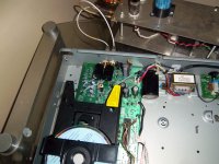
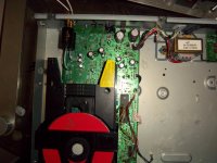
You can just see the regulator and the tant in the middle of the board.
It works extremely well and has really changed the sound for the better by a fair margin.
I'm now itching to feed the regulator with it's own ps.
I've found a small traf that'll give me about 18v once rectified so that's going in.. as soon as I've got the IEC socket sorted.
What do you think of your direct dac setup ?
Had time to listen ?
Looking forward to your findings...
Attachments
Glad you liked the change.
Improving the regulator will bring some extra benefits but always difficult to predict how much, always depends on other factors.
A better reg will clean up the incoming supply a lot but if you're adding a seperate tx anyway I would expect the supply to be fairly clean anyway.
Using leds to set the voltage on the 317 (instead of a resistor) will improve things as will adding a vbe on the input, both relatively easy and cheap to do. After that you're taking about something like a flea which starts to get expensive. I only added a flea with it's own tx so I can't rally comment on how much better it is that just a separate basic supply I'm afraid.
One thing though, 18v into the 317 is going to give a big voltage drop and may require a heatsink on the 317. If you're not going for something like a flea then a 9v tx should be more than enough. Even a 7v tx with schottky diodes will give around 10v.
I'm liking the direct feed from the dac more now that I have a better cap on it, I think it's a keeper. Just got to decide how esoteric I want to go with the cap (taking cost and size into consideration). I think I have some mundorf mkps in my cd67, I may take those out and try them, depends on how easily they will look to come out and maybe go back in
Regards
Pete
Last edited:
More bits arrived today and now just waiting for a 9v traf.
Found 3 excellent 5v super regs made by audio gd which I bought to put in an arcam alpha 5 a few years back.
Never got round to it and forgot I had them.
Maximum input voltage +15v so it's a good job I listened to you Pete and ordered a 9v traf instead of using the ones I had already ....haha
Nirvana awaits
Oh sure... that old chestnut again
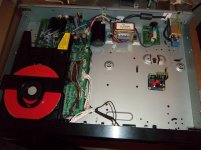
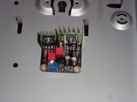
IEC now in plus a ferrite on the inbound and last pic is the little 5v regulator
going in to power the dac once the traff arrives.
I've got three of these regs and it's possible I can use all of them in here.
I know what I want them to do but it's about about where to put them physically.
Another 2 weeks maybe - still minus a clock though....
going in to power the dac once the traff arrives.
I've got three of these regs and it's possible I can use all of them in here.
I know what I want them to do but it's about about where to put them physically.
Another 2 weeks maybe - still minus a clock though....
Attachments
I've got three of these regs and it's possible I can use all of them in here.
You could use them all on the dac, there's 3 voltage inputs
pete
pete......I have a mayday
I've done something to it and it's odd
I changed the last original power supply lytic to bigger re dressed the coupling caps and moved the rca sockets to the left of the board ( to make room for a regulator ) snipped a couple of old unused small lytics on the original output stage off and finally changed 3 x 220 ohm carbon resistors that take bclk, sclk and data to the dac chip. The 3 resistors are side by side. I've checked my joints and anything else I could have disturbed and I can't find anything.
So, when I switch on the display is doing what it does correctly but is flashing every second and the sound is a kind of white noise with a bit of music in the distant background. It reads discs, changes tracks and there is 2.4 volts at the dac pins. Technically it's working in every way but is unhappy about something......any ideas ?
Bugger
Last edited:
Hi,
Not good
Did you replace the 3 resistors like for like (ohms), have you measured them after you put them in?
Only other thing I can suggest is maybe one of the bits that you removed wasn't related to the output stage?
The display flashing would maybe indicate that the problem is power related (possibly a short somewhere) but I've not come across these symptoms before.
No sure what else I can suggest apart from trying to put everything back as it was before the most recent changes.
Good luck
Pete
The resistors I used were 0.1 % tolerance original Holdsworthy era Holco's which I've not measured - so I ' assumed ' rather than check them. Maybe not so clever. I've examined over and over the joints and used my meter to affirm continuity from saa pins to 1st point and from 2nd point to the dac chip - they're good.
I whipped off three small caps in the area of the old output stage ( I didn't read the service manual beforehand ) ...silly perhaps ! I'll go back and replace these I think... and take out and examine what I've done when I changed the last remaining main ps cap.
I don't generally do ' shorts ' but having said that the local landfill site is filled mainly with my errors and explosions whilst learning so hey....it's all possible I suppose !!
I'll let you know - thanks for the heads up
The resistors I used were 0.1 % tolerance original Holdsworthy era Holco's which I've not measured - so I ' assumed ' rather than check them. Maybe not so clever. I've examined over and over the joints and used my meter to affirm continuity from saa pins to 1st point and from 2nd point to the dac chip - they're good.
I whipped off three small caps in the area of the old output stage ( I didn't read the service manual beforehand ) ...silly perhaps ! I'll go back and replace these I think... and take out and examine what I've done when I changed the last remaining main ps cap.
I don't generally do ' shorts ' but having said that the local landfill site is filled mainly with my errors and explosions whilst learning so hey....it's all possible I suppose !!
I'll let you know - thanks for the heads up
Check the resistance across the 3 resisters as well, make sure they're 220 within spec.
Check the 3 caps you removed against the manual, make sure that they were related to the output stage.
I've reversed the main power supply cap job and put a few small lytics back in ( 2 to go ) but I've been having a poke around with my meter too.
Believe it or not the voltage in to my regs is lower than the output of them and the voltage across ' the ' main large BHC capacitor is less than 4 volts...
That's not right
I'm going out for a new battery for the meter....it's getting silly now
The machine is functioning exactly as it should and in every way - display still blinking .
It's going to be something simple - I've looked for solder blobs or shorts made in error, polarity of caps checked, track damage, lifted pads etc....
None !
Hmmm you should be getting 10+ volts to the main cap (2536) if you're only getting 4 then either something else is drawing all the voltage or there is an issue in the circuit before that cap. In that case it can only be a faulty tx or an issue with the fuses or diodes. Maybe one of the fuses has blown, that would cut the voltage by half. I'd check the ac voltages where the tx plugs into the boards, at the fuses and at the diodes.
Regards
Pete
Regards
Pete
Started again - bought a new one.
Can't figure out my old problem but I'm determined not to rush this one to get it finished.
So, it's running direct off the dac already, Oscons in place, Tant bypass done, headphone socket off, op amp out and in the bin, 20mm mdf plank on the base plus rubber feet and finally all the wiring is much neater.
OK, I rushed the easy bits
I've a very decent 5v regulator ordered for the main supply, main supply caps to change, rectifier diodes ( not looking forward to that job again ) and other caps to do.
Still have the foils for around the dac to fit, the Shinkohs to go in when the new supplies for the dac are ready - which are not !
Then it's done....hahaha
Ooops, forgot the clock and loads of other things that'll reap the tiniest of gains that can hardly be heard... again
Has anyone clocked a Phillips 751 or a CD 48 ?
I'd love a very detailed explanation of that one - not had much luck with clocks.
It already sounds significantly better than stock ( and so it should ) and I'm fairly sure it's even sounding better with the mdf plank attached to the base.
The case is now almost completely inert, like a very dull thud.
Why would that work so well ?
I'm so pleased with this sound that I'll buy another 48 if I wreck this one too - not fazed at all.
Compared to what I had to do to an older TDA 1541 machine this is a walk in the park and has the potential to be significantly better - of that I'm sure
Hi Pete
That's a good idea - never thought of that.
I'll give it a go.
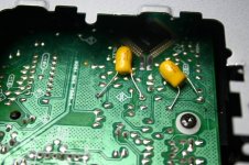
The pics say it all really.
I pinched the pic off the Lampizator site but it's much the same as mine.
Truth is I've no idea what benefit there is but hey, every one I've seen has this trick done.
It's below the SAA - you must have this chip too ?
There's blue Philips axials of 47uf on the other side of the board that the the tants are connected to.
That's a good idea - never thought of that.
I'll give it a go.
The pics say it all really.
I pinched the pic off the Lampizator site but it's much the same as mine.
Truth is I've no idea what benefit there is but hey, every one I've seen has this trick done.
It's below the SAA - you must have this chip too ?
There's blue Philips axials of 47uf on the other side of the board that the the tants are connected to.
Attachments
Last edited:
Bit of a development...
I just did the main ps smoothing caps but this time instead of the stupid ( idea ) large BHC cap laid down at the side connected to the board by wires ( as per the older pics ) I put newly purchased larger caps on the board where they should be - where the old ones were ( ashamed )
Well, the bass has taken on a life of it's own and reaches much further down and slams it home ( when applicable anyway )
It's a hugely satisfying gain and anyone who says these players don't do
' bass ' needs a rethink.
I've no bypass caps in yet and there's still plenty to do but if I can get this kind of ' order of magnitude ' again from what's left it's going to be stonking !
Grin inducing day
Have you done anything else Pete ?
Posh coupling caps in yet ?
I just did the main ps smoothing caps but this time instead of the stupid ( idea
) large BHC cap laid down at the side connected to the board by wires ( as per the older pics ) I put newly purchased larger caps on the board where they should be - where the old ones were ( ashamed ) Well, the bass has taken on a life of it's own and reaches much further down and slams it home ( when applicable anyway )
It's a hugely satisfying gain and anyone who says these players don't do
' bass ' needs a rethink.
I've no bypass caps in yet and there's still plenty to do but if I can get this kind of ' order of magnitude ' again from what's left it's going to be stonking !
Grin inducing day
Have you done anything else Pete ?
Posh coupling caps in yet ?
Hi,
I didn't do the tant bypass. I removed the original axial ecaps and put some bigger radial ones in instead (on the underside of the board, no room on top).
I've not got any posh output yet, but I did find some Wima MKP4s which I'm trying. Only put them in yesterday so still running in. Promising though. I'm not sure there's a lot of point going any better at the moment given that the signal will run through some worse caps on the input in my amp.
Regards
Pete
Hi Pete
If I follow your lead on putting bigger lytics underneath and remove the originals around the 5v supplies is there much to be gained ?
Also, the main 5v regulator....how much in the way of current is it working with generally speaking ?
The new regulator that's on it's way is good for 1 amp.
I've checked the data sheets on all the main receiving chips and if i'm correct by adding them together there's a lot less than an amp being drawn ( I think ) particularly now the op amp and the headphones are removed.
More so when I power the dac on it's own too.
Is a 1 amp reg OK to drop in where your super ray reg is ?

- Home
- Source & Line
- Digital Source
- TDA1549 - Marantz CD48