It's the Grundig DEM modification i did on a CD-960
CD 960 – Revisie – Bram Jacobse
I did some Measurements also
Dynamic Element Matching modificaties – Bram Jacobse
regards Bram
hi, yeah that's where I got the pic ��. although I cant get the page to translate. it's just I'm doing it on a CDA94
Hi,Does it work with NOS also, or only with 4x oversampling?
In NOS yes as I am using NOS not 4x oversampling.
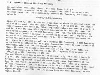
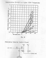
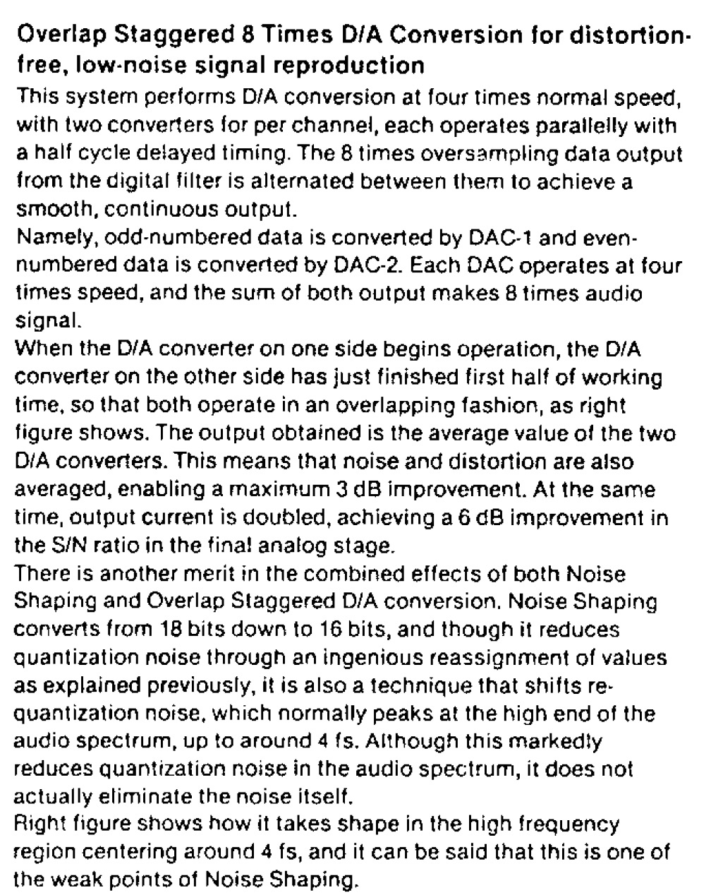
This is the information about DEM frequency. I think that is from some PHI book but I am not sure? This concept is used by the Grundig? Authors said that with increasing the DEM frequency more than 200KHz resulting rapidly increasing distortion, and they gave the graph of measurements.
Attachments
A few things I see in the document:
1. Distortion rises with fDEM >~250kHz
2. fDEM is internally divided by 4, and this frequency should never be within the audio pass-band (fDEM should not be <88.2kHz)
3. If fDEM is 176.4kHz, internally divided by four is 44.1kHz and being then the same as WS, less filtering is required.
4. 176.4kHz is suggested as being good compromise.
Last edited:
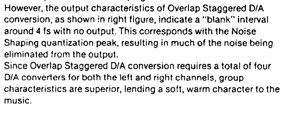
I also measured the Grundig DEM Modifictions
Sync with WS , at 176.4 kHz and 705.6 kHz sync with divided Bit clock
Measured in DIY CDD882")
Een CDD882 ombouwen naar een CDD882 Mk 2 – Bram Jacobse
Sync with WS , at 176.4 kHz and 705.6 kHz sync with divided Bit clock
Measured in DIY CDD882
Een CDD882 ombouwen naar een CDD882 Mk 2 – Bram Jacobse
Last edited:
This is the information about DEM frequency. I think that is from some PHI book but I am not sure? This concept is used by the Grundig? Authors said that with increasing the DEM frequency more than 200KHz resulting rapidly increasing distortion, and they gave the graph of measurements.
Does anyone know where to find the original document with pictures..?
Regards Bram Jacobse
I will try to find the capture in some PDF versions of Philips books? Because it is mentioning 470pF value this is from TDA1541 docs. But DEM is present at the TDA1540 version too with 820pF Cdem value.
.
Grundig version is the same - except values of 3Kresistor is 2.2K and 1K to GND is ommited.
.
Some of the DIY-ers claim thet this sygnal should be sinusoidal and not sync. with BCK. Others, that should be in sync with BCK, or LE...
.
I will try some isolation for the start like optocoupler at the pins.
now I am using so called free-running DEM on TDA1540 with original Cdem and 2 x 20K to -18V. It is 0.2mA across each 20K R to dem pins.
.
Grundig version is the same - except values of 3Kresistor is 2.2K and 1K to GND is ommited.
.
Some of the DIY-ers claim thet this sygnal should be sinusoidal and not sync. with BCK. Others, that should be in sync with BCK, or LE...
.
I will try some isolation for the start like optocoupler at the pins.
now I am using so called free-running DEM on TDA1540 with original Cdem and 2 x 20K to -18V. It is 0.2mA across each 20K R to dem pins.
In the past days I tried the Grundig mod, of course without the extra 6k8 resistors.
If I measure voltage at pin 16 & 17 without signal it is both -11,2V but is there is a signal at the dag pin 16 measures -10V and pin 17 -11V.
Could be ok or not I don't know.
Does somebody did this measurement?
-5, 5, -15 are within 0,05V so those are correct
Sound is perfect and I wil stay to the Grundig mod[emoji4]
Thanks.
My impression of the Resistor mod is that it was meant to suppress the noise created by the TDA's internal DEM clock (a couple of inverters and a external feedback capacitoor).Is it wrong to do rhe Grundig mod together with the 6k8 resistors on pin 16&17 to -15v?
The Grundig mod injects a clock with far less noise into the DEM circuit.
Whether the addition of one or two resistors could further improve on the Grundig mod, I can't tell. You could try and measure the jitter in both cases.
Unfortunately I don't have equipment to measure jitter. But I could put the resistors in place and listen.My impression of the Resistor mod is that it was meant to suppress the noise created by the TDA's internal DEM clock (a couple of inverters and a external feedback capacitoor).
The Grundig mod injects a clock with far less noise into the DEM circuit.
Whether the addition of one or two resistors could further improve on the Grundig mod, I can't tell. You could try and measure the jitter in both cases.
Unfortunately I don't have equipment to measure jitter. But I could put the resistors in place and listen.
Most people don't have that equipment or access to that kind of equipment. Indeed listening would be the only option.
However I understood from people having heard the Grundig mod and measured its performance that it's likely the closest to optimal. In my opinion the capacitor/resistors mod is quite good too.
However I understood from people having heard the Grundig mod and measured its performance that it's likely the closest to optimal. In my opinion the capacitor/resistors mod is quite good too.
Grundig mod is quit impressive indeed. I did the resistors alone also but Grundig mod the difference was more noticeable.
Maybe I will put the resistors in coming days.
I take a closer look at the Grundig CD9009 pdf
It is little different in wider angle:
- Parallel TDA1541A dac used - outputs for each channel tied together.
- I2S mode, BCK is same for each DAC chip. BCK is on Pin2 AND it is present at Pin4. Pin 4 is not used in I2S mode but it is from Time simoultaneous mode...
- DEM frequency is tied to WS and it is 156.4KHz over-sampled with Sony digital filter CXD1244S. Data are from PDF.
- CXD1244S have WS and -WS output. TDA1541A with data R, using -WS as DEM F. TDA1541A with data L using WS as DEM F.
- Data from CXD are in I2S standard BUT simultaneously going to dac inputs. Please take a look at the CXD pdf
.
I think that with one Latch period only one of the half DAC is active. And opposite half from another.
DEM fr is inverted with respect to data.
.
So for full implementation of Grundig mod (Philips book recommended circuit) probably deserves to apply all of these things. For Nos mode it will be hard. Because WS is 44KHz mostly. But DEM can be obtained dividing BCK. And Data are packed in different order in term of L/R. Data should be repack and separate into 2 lines. Somehow with some CPLD or some faster logic circuit module. Mistery is usage of pin4 which is reserved for Data Right in TS mode only. In I2S mode pin 4 remains unconnected?
Last edited:
A question. I did install the Grindig mod.
When measuring pin 16 & 17 without signal both have 11,34v but when signal is present pin 16 measures 9,88v and pin 17 10,88v.
Is this normal? Checked all connections and voltages and even another 1541a. It's always the same.
Thanks.
When measuring pin 16 & 17 without signal both have 11,34v but when signal is present pin 16 measures 9,88v and pin 17 10,88v.
Is this normal? Checked all connections and voltages and even another 1541a. It's always the same.
Thanks.
I also measured the Grundig DEM Modifictions
Sync with WS , at 176.4 kHz and 705.6 kHz sync with divided Bit clock
Measured in DIY CDD882
Een CDD882 ombouwen naar een CDD882 Mk 2 – Bram Jacobse
Hello BramJ.
I am an old man now
and dont get much time to do mods and cd alterations, but i did do that a lot in the early 90s till a cple of years ago.I just wanted to thank you for all the incredible info on Phillips units that you have made available through the years (your site).
It has certainly made for very interesting reading + lots of valuable insight into the incredible journey that made CD possible.
80's and 90's .... What an incredible era it was!
Keep up the good work!
best regards:
Alex
- Home
- Source & Line
- Digital Line Level
- TDA1541 DEM reclocking