hello, does someone have schematics for a parallel TDA1387 with passive I/U ?
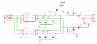
Not sure if this is what you're looking for, but see attached. This is a very simple, rudimentary tda1387-based DAC with passive I/V. There are two tda1387 chips in parallel. I have not tested this design! But I believe it is simple enough that it "should" work.
Attachments
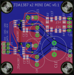
You're welcome! While I'm at it, here's a picture of the board for that circuit. I just submitted this to Elecrow for fabrication. So in 2-4 weeks I can tell you if it works or not. ")
It's not meant to be anything special, just a "warm up" for another project I'm working on. I'm having it fabbed mainly as a sanity check (and also because it's so cheap with Elecrow).
Looks like you're in the USA, so if you want a couple of these boards, let me know. When I get them, I'll give you a couple if you cover shipping.
Attachments
Nice, how much voltage can it put out in RMS ?
I'm not sure offhand... I stole the passive I/V circuit values from one of the tda1387 threads here on diyAudio. I may have taken them out of context, too, so there's a chance these values aren't right!
R1 and R2 are the I/V resistors. So you'd have to back out the voltage based on the current the tda1387 chips put out at a given power supply level (5V is what I specified for this board).
My plan was to wait until I got the boards, then actually sit down and do the math to make sure all the I/V values make sense. But I'm not 100% sure how to do that offhand, so I need to track down some old threads and review first. Hence, why I'm putting it off.
For a 5V supply the I/V resistors are a bit on the high side, given the DAC puts out 1mA maximum and the output compliance is 0 to 3.5V. It would be safer to fit 3k3. The output per phase then would be just a little over 1VRMS, taking two phases together would more or less match the CD standard of 2VRMS.
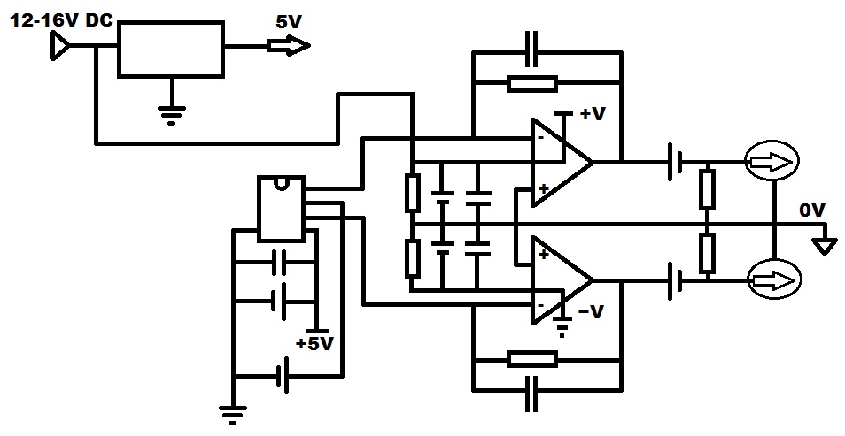
Hello folks, after finishing passive i/v for both tda1387 and a tda1543 DAC i wanted to try opamp approach (a good way to learn and ear differences).
First with some headphone amplifiers and then with DAC's.
I got a tda1543 working with this kind of schematic (a while ago) with Vref tied to the virtual ground through a resistor (variable for precise adjustment) but I can't get a functionnal tda1387 (Vref tied to ground or virtual ground through a capacitor) using the same topology.
I tried multiple variants (even one using transistors) to split the rails and the resuslts are all the same, the only way I was able to make it works is by using a dedicate power supply for the opamp section.
Sorry in advance if that sounds dumbs but what am I doing wrong or missing ?
Could this just be as simple as a ground issue (i did not tried with a refined star ground topology yet but i'm tired of experiments on bread board or protoboard that goes in smoke or just appear to be stone dead) ?
Could a lm317/lm337 rail splitter be able to fix this or I definitely need a separate power supply or a complete new design ?
Thanks in advance
Simplified view of the design (hope this explain it all at first glance) :
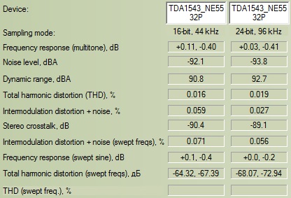
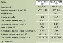
Results obtained with my single TDA1543 DAC using 2 NE5532P with their second half used as a buffer (why not ?).
For me it looks pretty decent for a first DAC/Opamp try :
First with some headphone amplifiers and then with DAC's.
I got a tda1543 working with this kind of schematic (a while ago) with Vref tied to the virtual ground through a resistor (variable for precise adjustment) but I can't get a functionnal tda1387 (Vref tied to ground or virtual ground through a capacitor) using the same topology.
I tried multiple variants (even one using transistors) to split the rails and the resuslts are all the same, the only way I was able to make it works is by using a dedicate power supply for the opamp section.
Sorry in advance if that sounds dumbs but what am I doing wrong or missing ?
Could this just be as simple as a ground issue (i did not tried with a refined star ground topology yet but i'm tired of experiments on bread board or protoboard that goes in smoke or just appear to be stone dead) ?
Could a lm317/lm337 rail splitter be able to fix this or I definitely need a separate power supply or a complete new design ?
Thanks in advance
Simplified view of the design (hope this explain it all at first glance) :
Results obtained with my single TDA1543 DAC using 2 NE5532P with their second half used as a buffer (why not ?
). For me it looks pretty decent for a first DAC/Opamp try :
Attachments
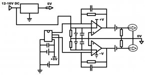
Looking at your schematic I can't see a reason why the output RCAs should have 0V as their common, I reckon you'll be better off with the earth symbol connected to them.
Thanks, to be honest i just wanted to have the opamp i/v section and output separated from the rest of the circuit and though it would lower the noise present in the signal.
And if i'm not wrong or remember correctly this is also the way it is done with cmoy types headphones amplifier but now i'm not really sure anymore...
So, can I share this part with the line where there is also return path for i2s shielding without concern for noise ?
In this case, should filtering ceramic caps present at OPA supply inputs be tied to real ground or only virtual ?
What's the best path in therm of noise reduction, or doesn't this matter at all as long as group all the return path of the parts (except OPA) at the same point ?
As soon as i get some free time i will try this and check again if the components presents on the bread board makes good contacts.
Anyway this is an interesting matter for sure.
Thanks again for your precious thoughts.
I had a bit of time today and finally make it work
I tried a different approach to supply both the dac and the opamps though (by using two adj voltage regulator in series). Easiest way i had at hand to get two stable fixed voltages of 10V and 5V (using AMS1117) with a 16V supply.
Talk about shame, i spendt almost a week before to test differents topologies and values both on breadboard and protoboard only to find that some of the opamps used where dead from the start (forgot to bin them)
That led me to try the dumbest things i ever did with components and appreciate the sweet smell of burning parts
Now i feel so bad to have asked suchs questions which 3/4 of the answers where in the datasheets and schematics i drew on sheets of papers months ago.
Time to get the best of this single TDA1387
What didn't you like about paralleled 1545's?
This DAC with 8 paralleled TDA1387s sounds just great to my ears - http://www.diyaudio.com/forums/digi...-check-its-design-mod-not-play-music-not.html
I am looking into ordering this version, I like the passive output (in TDA1543 style). Just some observations:
- the power supply power transistors float on the bottom, are they isolated from the house?
- The chips have a 10 nF decoupling - is that on pin 7? Could these be connected together all 8 and combined to one larger buffer? (the hexa’s won’t fit in the case I’m afraid.) From my experiments with the 1543 I know there are slight differences bewteen the natural ref voltage given the same Vb and Vout.
- Some buyers complained about some static and bad sound. Circumstantial or endemiwc?
The larger case version this thread is about is not readily available. it is on taobao but of course not with int ordering/shipping.
Which DAC with passive out are you talking about? There is this one, which has transistors in contact with the case. They're output transistors though for the headphone amp not power supply elements.
L1387A 8X 解码1969纯甲耳放一体机TDA1387八并联挑战TDA1541力作-淘宝网全球站
L1387A 8X 解码1969纯甲耳放一体机TDA1387八并联挑战TDA1541力作-淘宝网全球站
Yes Abraxalito, This is the one. Thanks.
So this floating is no problem then, maybe just take care for isolation, no big heat build up. (Does 1969 refer to a class A JLH design?)
How should I add the larger capacitor bank? I have 10mm dia 3 cm high 3.300 muF 6,3 Volt caps, 8 or even more available.
Any other changes? To get rid of higher images that will give the effect of 'lispelen' (dutch), 'lisping' (english): the idea is a faint echo in high frequencies itthatis reminiscnent of an FM receiver that is not correctly tuned, f.i. when there are extra antenna images.
Last edited:
Since recommending adding caps to the rails, I've learned a little bit and found a more effective way to improve the bass - use active I/V and preferably add a low-pass filter. If you go that way you won't need to add any extra caps. I'll be putting the full schematics up on Hackaday eventually, right now just the filter and I/V stage is shown - Audiophile-sounding DAC for almost no money | Hackaday.io
Yes Abraxalito, This is the one. Thanks.
So this floating is no problem then, maybe just take care for isolation, no big heat build up. (Does 1969 refer to a class A JLH design?)
How should I add the larger capacitor bank? I have 10mm dia 3 cm high 3.300 muF 6,3 Volt caps, 8 or even more available.
Any other changes? To get rid of higher images that will give the effect of 'lispelen' (dutch), 'lisping' (english): the idea is a faint echo in high frequencies itthatis reminiscnent of an FM receiver that is not correctly tuned, f.i. when there are extra antenna images.
I suggest you skip on that DAC, I have one and the case extremely hot to touch, around 50 degrees Celsius. I am not impressed with the sound either.
Kind regards
Marko
I have a couple of these DACs but I've not used them. I opened one up last night and noticed the I/V resistors are 620ohm - this is too high given the output current (1.08mA*8=8.64mA peak). So the very least mod to do would be to reduce their value to ensure no clipping. I calculate the resistance to remain within the 3.5V maximum compliance as 390ohm.
Could be it sounds bad due to running into clip - the choice of 620ohm is a design error.
Could be it sounds bad due to running into clip - the choice of 620ohm is a design error.
Last edited:
Okay ... I'm using only one TDA1387 in a NOS cd player.
I use the TDA1387's data-sheet-specified 1-uF cap (C4) from pin 7(REF) to pin 4 (GND). No problem -- good sound.
Then I changed C4 to a high value (1000-uF), as suggested (??) in this thread (??).
Result: no sound and mid-level hum.
Change C4 back to orig. 1-uF. No problem -- good sound.
What did I miss?
Last edited:
Okay ... I'm using only one TDA1387 in a NOS cd player.
I use the TDA1387's data-sheet-specified 1-uF cap (C4) from pin 7(REF) to pin 4 (GND). No problem -- good sound.
Then I changed C4 to a high value (1000-uF), as suggested (??) in this thread (??).
Result: no sound and mid-level hum.
Change C4 back to orig. 1-uF. No problem -- good sound.
What did I miss?
At the risk of patronizing you, are you sure the polarity of the cap was correct? Positive to pin7, negative to ground? What kind of cap was it? Are you sure the cap is good?
Do you have any other caps with which you can test?
There are several threads where added capacitance on pin7 has been mentioned as a good thing. I'd call it standard practice at this point.
But it's been done by many forum members here, including me, so I don't think there's anything fundamentally wrong the the idea.Any chance we can see some pics?
At the risk of patronizing you, are you sure the polarity of the cap was correct? Positive to pin7, negative to ground? What kind of cap was it? Are you sure the cap is good?
Do you have any other caps with which you can test?
Yes double-checked polarity before posting query.
It's a Jamicon 1000uF/50 v. It's new and my ESR meter indicates it's good.
Will have to check other caps ... sty tuned.
- Status
- This old topic is closed. If you want to reopen this topic, contact a moderator using the "Report Post" button.
- Home
- Source & Line
- Digital Line Level
- TDA1387 continuous calibration dac