Re: more follow-up
You can certainly feed V- on pin 3, also eliminating the output capacitor. Don't forget the total DC voltage specified by manufacturer.
Many of these chips were designed for car amps, and by making a bridge you can do your output without any capacitor and increase your power.
Carlos
sangram said:
Any reason why this circuit cannot work in split supply mode? I don't see one but I wonder why the datasheet would specify a single supply for this sort of application.
You can certainly feed V- on pin 3, also eliminating the output capacitor. Don't forget the total DC voltage specified by manufacturer.
Many of these chips were designed for car amps, and by making a bridge you can do your output without any capacitor and increase your power.
Carlos
Re: Re: more follow-up
Thanks
")
The TDA 2030 operates at upto 44V single or +-22V. Lots of headroom at +/- 16V. Might be nice with a pair of SLAs. I'm also trying out a circuit with Thorsten's Unity-gain stable schematic idea.
Too many chips, too little time.
Sang
carlmart said:
You can certainly feed V- on pin 3, also eliminating the output capacitor. Don't forget the total DC voltage specified by manufacturer.
Many of these chips were designed for car amps, and by making a bridge you can do your output without any capacitor and increase your power.
Carlos
Thanks
The TDA 2030 operates at upto 44V single or +-22V. Lots of headroom at +/- 16V. Might be nice with a pair of SLAs. I'm also trying out a circuit with Thorsten's Unity-gain stable schematic idea.
Too many chips, too little time.
Sang
Re: Re: Re: more follow-up
It would also fit the bill in the bridging/paralleling thread I started.
You can power it all +/-16v with plenty of power and headroom. I'd expect at least 60w into 8 ohms for such arrangement., in bridge/parallel, with the capability of much more into 4 ohms allowed by the parallel sharing.
Carlos
sangram said:The TDA 2030 operates at up to 44V single or +-22V. Lots of headroom at +/- 16V. Might be nice with a pair of SLAs. I'm also trying out a circuit with Thorsten's Unity-gain stable schematic idea.
It would also fit the bill in the bridging/paralleling thread I started.
You can power it all +/-16v with plenty of power and headroom. I'd expect at least 60w into 8 ohms for such arrangement., in bridge/parallel, with the capability of much more into 4 ohms allowed by the parallel sharing.
Carlos
Re: Re: Re: Re: more follow-up
Doubtful, actually. The 2030 is limited in terms of O/P current - 3.5 amps before limiting, so maybe 3 amps or so. A single set of bridged ICs will put about 30W into 8R (I'm talking within usable distortion figures). A parallel + bridge would be required for 60W or so, but then that's 4 ICs and for that many chips/components/heatsinks a single TDA 7294 is probably better...
I have the datasheet in case you're looking for candidates...
carlmart said:
It would also fit the bill in the bridging/paralleling thread I started.
You can power it all +/-16v with plenty of power and headroom. I'd expect at least 60w into 8 ohms for such arrangement., in bridge/parallel, with the capability of much more into 4 ohms allowed by the parallel sharing.
Carlos
Doubtful, actually. The 2030 is limited in terms of O/P current - 3.5 amps before limiting, so maybe 3 amps or so. A single set of bridged ICs will put about 30W into 8R (I'm talking within usable distortion figures). A parallel + bridge would be required for 60W or so, but then that's 4 ICs and for that many chips/components/heatsinks a single TDA 7294 is probably better...
I have the datasheet in case you're looking for candidates...
Re: Re: Re: Re: Re: more follow-up
No, thanks! I'm staying with the National chips for now, perhaps later trying some 7294 if I can get samples of.
I wasn't aware of that hard current limiting in the 2030. Sharing the current might allow a bit more, but who knows?
The tests I will do will use LM3886 and OPA549.
Carlos
Carlos
sangram said:
The 2030 is limited in terms of O/P current - 3.5 amps before limiting, so maybe 3 amps or so. A single set of bridged ICs will put about 30W into 8R (I'm talking within usable distortion figures). A parallel + bridge would be required for 60W or so, but then that's 4 ICs and for that many chips/components/heatsinks a single TDA 7294 is probably better...
I have the datasheet in case you're looking for candidates...
No, thanks! I'm staying with the National chips for now, perhaps later trying some 7294 if I can get samples of.
I wasn't aware of that hard current limiting in the 2030. Sharing the current might allow a bit more, but who knows?
The tests I will do will use LM3886 and OPA549.
Carlos
Carlos
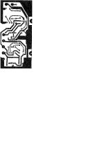
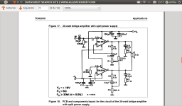
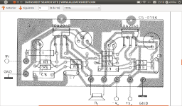
This PCB i taked from the datasheet of TDA2040 in mode bridge but whit TDA2050 or if you want whit TDA2040 or TDA2030.
And sorry don't speak good english
And sorry don't speak good english
Attachments
This PCB i taked from the datasheet of TDA2040 in mode bridge but whit TDA2050 or if you want whit TDA2040 or TDA2030.
And sorry don't speak good english
I forgot tell something, If you gonna use TDA2050, got to change the the C2, C6, by 470 mF 25V, C8 and C9 by 470nf 100V min, R8 & R9 by 2.2 ohms / 1 watt.
That's all.
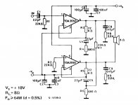
New better version
Hi everyone, i was do a remake of this last proyect sended but more serious, ready to build, enjoy it!
Size: 3.5 x 7.75 [cm]
Hi everyone, i was do a remake of this last proyect sended but more serious, ready to build, enjoy it!
Size: 3.5 x 7.75 [cm]
Attachments
Last edited:
.
With balanced (XLR) lines, the dual input is actually reduced to a single audio signal, then that single audio signal is sent through the amp, preamp, or whatever.
At the output of the amp/preamp/whatever, if desired, the single audio output is split into two outputs for a balanced line, and these are sent on to wherever.
This might be of interest: Balanced Line Driver & Receiver
.
Ups!!!!
Sorry don't put two points one by C4 and R1 to ground that's correct SORRY :S
Hi everyone, i was do a remake of this last proyect sended but more serious, ready to build, enjoy it!
Size: 3.5 x 7.75 [cm]
Sorry don't put two points one by C4 and R1 to ground that's correct SORRY :S
Attachments
- Status
- This old topic is closed. If you want to reopen this topic, contact a moderator using the "Report Post" button.
- Home
- Amplifiers
- Chip Amps
- tda 2050 gainclone / balanced input?