Balanced gainclones
Mad_K,
There's something you should be aware of when using balanced inputs: CMRR.
CMRR figures have to do with noise rejection, which is why balanced is used at all. It has a problem: it's not linear. To make it linear, on a transfomerless circuit, you have to adjust the resistors and capacitors that set the gain so they match each other.
If you don't do so your figures may not be too good. For instance: on the PM21 diagram you would use trimmers instead of C4 and R6 and adjust high and low response respectively. Get it?
Or you can match your resistors (in pairs) and caps as much as you can and accept lower figures. For this application it wouldn't be too serious, IMHO. That's what Marchand probably does too.
Carlos
just thought i'd breathe a bit of life back into this thread.....
i've got my mind made up to build the bpa-200 (national appl. notes) bridged and paralleled lm3875. i am now toying with the idea of running it balanced. would there be any problems with this, or anything i should be careful of? any info would be most appreciated. i realise this is probably pretty easy stuff to most of you, but even if you just point me in the right direction i would be much obliged.
Thanks in advance (hoping i will get an answer)
Mad_K said:Thank you Halo!!!")
BTW, how do you ripp pdf's like that? (Not with a scanner, I hope...)
If you press ctrl|Print Screen you will capture the active window, then you can paste into whatever graphic editing program you have. No need for a special program for this.
Shift|Print Screen captures the whole screen.
i'll say it again,
goin' balanced - use a drv-134......
Hope you meant; INA134...receiver...?
Arne K
SvErD said:
If you press ctrl|Print Screen you will capture the active window, then you can paste into whatever graphic editing program you have. No need for a special program for this.
Shift|Print Screen captures the whole screen.
Thanks for the info. If you only press Print Screen, you capture the whole screen also
Bridge
That is you will be bridging the chip's output.
In fact you can try inverted mode on both sides and get an inverted bridge.
Carlos
tbla said:if you have a single ended input goin' to the drv-134, and out comes a very nice balanced signal you can use to drive the 2 sides of poweropamps.....
That is you will be bridging the chip's output.
In fact you can try inverted mode on both sides and get an inverted bridge.
Carlos
tbla,
i get where you are coming from with the drv134, but what is troubling me is, where do i run the chips to ground? to the negative signal for the positive, and vice-versa? routing the wiring wrong could really turn out bad. this is probably a little adventurous for me, but i'm slowly getting there. (i have the drv134 chips on order )
if they get the gainclone-x sorted, i might try incorporating that too. the possibilities are endless........
i get where you are coming from with the drv134, but what is troubling me is, where do i run the chips to ground? to the negative signal for the positive, and vice-versa? routing the wiring wrong could really turn out bad. this is probably a little adventurous for me, but i'm slowly getting there. (i have the drv134 chips on order
)if they get the gainclone-x sorted, i might try incorporating that too. the possibilities are endless........
Hamish said:tbla,
i get where you are coming from with the drv134, but what is troubling me is, where do i run the chips to ground? to the negative signal for the positive, and vice-versa? routing the wiring wrong could really turn out bad. this is probably a little adventurous for me, but i'm slowly getting there. (i have the drv134 chips on order
if they get the gainclone-x sorted, i might try incorporating that too. the possibilities are endless........
Maybe my new thread will help you.
Carlos
tda 2030a
I picked two of these puppies yesterday.
I've already assembled one of them.
It sounded sort of OK last night, thin bass, lots of top end, very 'IC' sound. Not particularly great. I've used off-the shelf components, no audio grade stuff, the only compensation are 1% MFRs as opposed to 5% carbon, and a tantalum input cap. The heatsink is a dubious type, meant for small TO-200 transistors. Wouldn't trust them: after about 10 minutes they get extremely hot. They're fine on idle though, so I guess the amp is not oscillating... I'm going to have to put them onto a better set of sinks.
PSU is based on a 12/0/12 Transformer (+/- 16V rails) at which the datasheet promises 15 watts into 4R. 5600 uF per rail on PSU, with film cap bypass throughout and small 100uF decoupling caps. Wiring is all directly on the chip's pins (I'm so proud!) and am planning on damping thoroughly with silicon sealant to damp any vibrations/etc. I still need to figure out a way to get high-power connections safely on to the power supply pins of the IC.
This morning it sounded better, more weight in the bass, clearer and less sharp top end, I think the chips hold promise. After comparing datasheets I decided I could live with a little less power than the 2040: the 2030a seemed slightly better specced. For about 60 cents, the chip is a great buy. I can easily look at bi-amping and triamping for a pair of studio monitoring speakers.
more follow-up
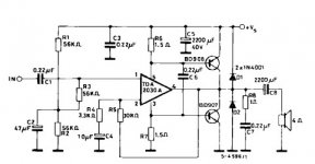
Also looking at a driver circuit.
Any reason why this circuit cannot work in split supply mode? I don't see one but I wonder why the datasheet would specify a single supply for this sort of application.
Of course making the correct modifications for dual supply operation - I do not see I will have to add any components, maybe substitute the o/p transistors with TIP3055/2955 to which I have ready access, maybe add BC548/558 to compensate for lousy Hfe figures of the 3055 set. Remove the output cap, and the voltage divider. R3 returned to ground, and reduce the amount of feedback. I am currently operating at about 22/23 dB closed loop gain, with no apparent instability, and a much lighter zobel (4.7R/0.1 uF).
Unless, of course there is a very good reason for the amp to be specified for single and not dual supply... Can I remove the protection diodes if I use a few turns of ECW on the output in series?
I also assume that P2P or on-chip soldering will be close to impossible for this application, and am ready to start looking for a suitable PCB.
Also I will start applying some of the gainclone mods on the circuit once I have a boarded prototype ready to go. Maybe the 'Class A' mod.
I will also rig up a prototype which abandons the use of MFRs and tantalums, and uses lousy generic components, just for fun... I also have some SLAs. Maybe I can try running this thing off a pair since I've heard so much about the use of batteries to run amps...
The total cost of one of these modules excluding the heatsink and Power supply is about $1. Not bad, eh? Not too much power, but what do you get for one lousy buck anyway?
Also rewire the second prototype: Mine is starting to look messy now, since I twisted component leads first and then proceeded with attaching them onto the IC pins (a webcam, a webcam, my kingdom for a webcam - or maybe not). All components are suspended in thin air with only the rigidity of the IC pins holding them in place. Silicon sealant may or may not be enough to damp the entire circuit...
Maybe a small veroboard for passives with some wire wrap leads extended for the IC mounting (impossible to mount this beast on a veroboard). Unfortunately veroboards have very thin tracks, so some beefing up required on this front... This is the main reason I did not veroboard the amp in the first place, so...
Attachments
- Status
- This old topic is closed. If you want to reopen this topic, contact a moderator using the "Report Post" button.
- Home
- Amplifiers
- Chip Amps
- tda 2050 gainclone / balanced input?