Well, Xmas doesn't really exist in the corner of the world I live right now, but I continue to believe... ")
Made a quick and dirty sweep of both the woofer and tweeter.
I looked at the XO that TB posted online and was not excited.
Came up with my own with parts I had at home.
Had one driver in a vented box, wired the XO and had a quick listen at low volume (late in the evening here now) and sounded ok... a bit of sibilance but I'll let the drivers break in for a while before passing judgment.
Attachments
When it comes to sibilance how do you know it is not on the recording?
I have a few other pairs of speakers here at home that were dialled in pretty nice.
And I usually use the same tracks here to weigh in the different designs. Tracks that I know very well. Tracks that will show and tell... being right on the edge between great and overdoing it.
There will be more tweaking ahead... and I will give the W6-2313 a bit more time to break in. Barely a couple of hours on them.
And the real measurements are coming.
But I have a couple of other projects to finish before I can tackle this set of drivers.
All in good time.
Last edited:
I do appreciate that they have a unique look, but I do care about how they sound!!
On the physical side, they have some weight when in your hands. The ribbed surround to paper to shiny centre ring is seamless and looks quite good. Combined to the tweeter grill, it does make the driver stand out. I will try to come out with something to show it off a bit.
I'm not a great fan of the 2 layer bezel, held in place by screws and having those protruding dots all around... but I'll get over it.
One strange thing... there was a loose screw stuck to the magnet when I opened the box. I looked everywhere on the driver, and there doesn't seem to be a screw missing, so I guess it was a stray.
And some measurements...
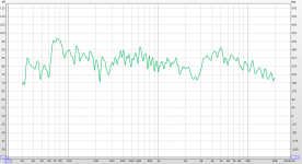
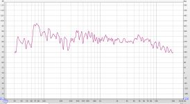
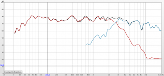
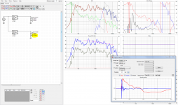
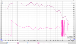
Found the sibilance culprit... the tweeter has a peak at 5kHz.
I changed some parts in the XO and it got a little better. I'll need to consider adding a small notch at 5kHz.
The green (first XO) and red (new XO) lines are at listening position, close to 2m away.
The blue is taken at 50cm. There's some phasing issues around 8kHz.
The dip between 200 and 300 is room and speaker position related.
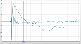
There is something peculiar with the impulse though. I'll have to investigate if the double peaks are between the woofer and tweeter, or if I was a bounce close to the speaker.
That's it for now... I have a couple of extra things on my plate, so this is a little slow...
Found the sibilance culprit... the tweeter has a peak at 5kHz.
I changed some parts in the XO and it got a little better. I'll need to consider adding a small notch at 5kHz.
The green (first XO) and red (new XO) lines are at listening position, close to 2m away.
The blue is taken at 50cm. There's some phasing issues around 8kHz.
The dip between 200 and 300 is room and speaker position related.
There is something peculiar with the impulse though. I'll have to investigate if the double peaks are between the woofer and tweeter, or if I was a bounce close to the speaker.
That's it for now... I have a couple of extra things on my plate, so this is a little slow...
Attachments
I think there might be a difference in acoustic center, even though the tweeter is placed at what seems to be the center of the woofer. Can you measure that? In Xsim I had to add a 0.65 inch delay on the woofer to get the measurements to correlate with the simulation.
Can you show the tweeter and woofer traces together with the sum? And what is current XO?
/Anton
Can you show the tweeter and woofer traces together with the sum? And what is current XO?
/Anton
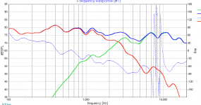
I need to work on the sim because it does not follow too closely... especially when I invert the tweeter, which gives a much better FR. I tried playing with delay a little, but no luck.
I'll measure the woofer and tweeter separately next time.
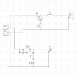
In XSim, this is my XO:
I'll measure the woofer and tweeter separately next time.
In XSim, this is my XO:
Attachments
Last edited:
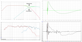
Changed the XO to the one I posted in the earlier pages.
Busy day, but I took 10 min to do a quick sweep of the woofer, the tweeter and both, using the XO.
Impulse still is not clean, and I'm afraid that there can't be anything done about it, unless going active to adjust the delay between both.
Busy day, but I took 10 min to do a quick sweep of the woofer, the tweeter and both, using the XO.
Impulse still is not clean, and I'm afraid that there can't be anything done about it, unless going active to adjust the delay between both.
Attachments
Hi perceval looks like you try target a transient perfect step using normal polarity for both pass bands, if you want that feature slopes most be of 1st order or a complicated hybrid of B&O filler concept or Harsch, slopes you have now looks close to 2nd order LR and for that you need flip ones polarity and live with that phase turn, well its probably best or most correct flip tweeter if you want to integrate speaker with other systems such as a sub or AV system. Probably also you have some acoustic center mitchmatch else it would have looked worse than now when both are in same polarty, suggest you start find out that exactly number of acoustic center offset because it would help you use that number into design software for whatever slopes you try to target.
Okay it gives a dip with flipped polarity, then think that would indicate some acoustic offset is in place, with spaced apart summing drivers one can change design axis to counter for offset but will not work for coxials, looking at your IR/SR graphs it seems woofer is in front.
Will probably try trace your curves into VirtuixCAD and see what it comes up with in relative offset.
Will probably try trace your curves into VirtuixCAD and see what it comes up with in relative offset.
Byrtt, I'm so sorry.
It's a busy day, and my wiring to do the XO is a mess.
The FR that looks better is with inverted polarity with one driver.
It gives a dip when they are the same polarity.
Sorry for the confusion.
I tried a bunch of things and it was hard to keep up with it in my mind, since I am also tackling another build for a friend, and Xmas activities starting today at our work...
Okay it had a dip with same polarity as it should for 2nd order so you flipped tweeter around, no problem the little confusion and have a best Xmas plus busy work time
Loading your curves into VirtuixCAD it looks tweeter is in area somewhere 10-25mm (29-72uS) behind woofer, in below tweeter is set 10mm behind and IR/SR plus response summing starts to look as your live curves. DSP can cure that offset but also XSim has allpass networks baked into "CircuitBlocs" menu that probably should be able set a delay for woofer band but probably it gets expensive in components.
Loading your curves into VirtuixCAD it looks tweeter is in area somewhere 10-25mm (29-72uS) behind woofer, in below tweeter is set 10mm behind and IR/SR plus response summing starts to look as your live curves. DSP can cure that offset but also XSim has allpass networks baked into "CircuitBlocs" menu that probably should be able set a delay for woofer band but probably it gets expensive in components.
Attachments
Hi perceval i had a recheck of slopes into Rephase using its compensate mode and actual it looks LP of woofer is close to a 4th order LR at 2400Hz and HP of tweeter is close to a 3rd order BW at 2800Hz, so the flip of polarity is probably what it needs to compensate acoustic center offset.
Summing those two slopes over in REW with one polarity flipped gives below summing with and without a 1mS offset.
Summing those two slopes over in REW with one polarity flipped gives below summing with and without a 1mS offset.
Attachments
oops...
I just tried adding an all pass 1 st order on the woofer, and it just crashed XSim.
I looked at the 2nd order.. and yes, a bit complicated and way too many parts to make it expensive. I actually like when there is not too many connections and parts between the amp and the sound heard.
I'll give it a try again later.
Ok...
word to the wise...
be very careful with the woofer connect tabs. They are awkwardly placed and a bit wider than the fit of the bezel and very easy to break off.
I just broke one side by just placing the driver into the hole.. not forcing it or anything.
The rest of the driver is very sturdy... but the tabs are very flimsy and protruding.
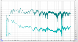
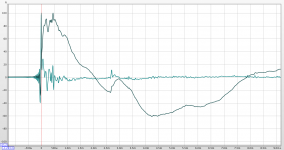
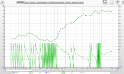
Progression.
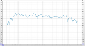
I wasn't happy at all with the last XO. It just didn't sound right.
I simplified things and started cleaning it up.
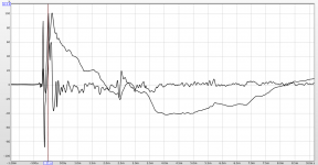
Good step forward and finally starting to sound right.
Impulse has cleaned up, FR is reasonable and phase is behaved.
The XO point is much higher at 4.3kHz. I know it's a bit limit as the woofer is probably starting to beam a little. So, next step will be to measure on and off-axis.
For now, I'm pretty happy.
I wasn't happy at all with the last XO. It just didn't sound right.
I simplified things and started cleaning it up.
Good step forward and finally starting to sound right.
Impulse has cleaned up, FR is reasonable and phase is behaved.
The XO point is much higher at 4.3kHz. I know it's a bit limit as the woofer is probably starting to beam a little. So, next step will be to measure on and off-axis.
For now, I'm pretty happy.
Attachments
- Home
- Loudspeakers
- Multi-Way
- TB new line of Coax FR drivers