Before I dive into this topic, a few caveats:
- I've built and measured a pile of speakers over the past couple decades, and I've noticed that the computer simulations of bandpass and vented boxes rarely match reality, particularly in a room.
- IMHO bandpass boxes are one of the most unforgiving box designs, because leaks screw up the helmholtz resonance. I've seen leaks that were the size of a pinhead that have altered the frequency response! And when you think about the pressure that's being exerted on the chambers in a bandpass box, you can see why a leak that's invisible to the naked eye will have an effect on the output.
Whenever I've built a vented or BP box and measured it outside it has been very close to the model from winISD. You have kind of answered why your boxes do not measure properly in the latter part of your post. Maybe try coating the insides of your boxes with fibreglass resin to seal up all the gaps ? If the boxes you are building are leaky then you are going to wreck drivers, regardless of whether they are cheap or expensive.
What I see in these pictures is a piece-of-junk car audio driver with many design compromises, it's intended to be used only in sealed boxes. A vented box with a single big port in one corner could have produced exactly the same result.
Excursion capability is high, power handling is high, but the design is extremely weak when it comes to handle the cone tilt resulting from uneven acoustical load around the cone and high excursion. That's what produced the rubbing of the voice coil against the pole piece. The driver is not intended to work against a hard and uneven air load (the scenario in most horns).
To make it worse, the spider is very far from the pole piece, so any minor cone tilt results in great deviation of the voice coil from the center. The donut style rubber surround makes it even worse because it does not provide any cone centering effect either.
Such a driver would require at least a symmetrical taped horn or symmetrical ports in a vented box. Anyway, a dual spider driver, or any driver with the spider closer to the pole piece, or just any driver with a cloth surround would be much more reliable in such a tapped horn (for example, almost all pro-audio subs).
Furthermore, one layer of the voice coil got almost completely unwrapped but there are no signs of darkening, so heat was not involved at all. I think it was just due to the lack of quality and quantity in the enamel used to put the magnet wire together and/or improper curing.
Low cost Chinese car-audio subs? No thanks
Wow Eva...
I was sure i had NOT over powered it...
I could not see any Dark anywhere on the coil ! it just came apart / so i looked into the gap and saw where the slugs were NOT alined and the coil former had struck it...
I can't say that it was overpowered, but given the magnitude of the rubbing in the voice coil, it's obvious that you powered it quite well in the bottom octave, where it hurts most for that combination of weak speaker and heavy air load.
Didn't you notice the rubbing? It should have been quite obvious for anybody capable of telling bass from noise.
in the bottom octave, where it hurts most for that combination of weak speaker and heavy air load.Didn't you notice the rubbing? It should have been quite obvious for anybody capable of telling bass from noise.
He should'a just monitored his displacement and limited accordingly to prevent damage: http://www.diyaudio.com/forums/subwoofers/153359-reading-driver-displacement-radar.html
Wow Eva...
I was sure i had NOT over powered it...
I could not see any Dark anywhere on the coil ! it just came apart / so i looked into the gap and saw where the slugs were NOT alined and the coil former had struck it...
But, you did.
While perhaps a bit blunt, Eva's analysis is spot on. djk and sssnake also stated the same thing. This driver was driven too hard and was damaged by overexcursion. It sure looks like the coil left the gap and struck the pole piece when re-entering.
In order for this to happen, the driver was overpowered for the enclosure it was in. There may be other issues as well that led to the failure you experienced, but the driver had to be overpowered for the enclosure you had it in for the failure to take place.
Too much thermal power is one thing.
Overexcursion due to too much power applied (within the driver's thermal limit) is another.
Physical damage kills woofers dead. I know, I have.
All we are trying to point out is is that too much power in some types of enclosures (such as yours) leads to too much excursion, which causes physical damage to the coil or driver long before the coil smokes. Patrick's simulation shows that quite clearly. A different tapped horn design might have kept the driver alive longer. A subsonic filter definitely would have.
The more complicated the enclosure design, the more you have to know about the driver being used, and the worse things get when stuff goes wrong.
+1In order for this to happen, the driver was overpowered for the enclosure it was in.
Whenever I've built a vented or BP box and measured it outside it has been very close to the model from winISD. You have kind of answered why your boxes do not measure properly in the latter part of your post. Maybe try coating the insides of your boxes with fibreglass resin to seal up all the gaps ? If the boxes you are building are leaky then you are going to wreck drivers, regardless of whether they are cheap or expensive.
I wish I could say that I've had predictable results from WinISD. In every instance, I've had to adjust the length of ports to get the tuning frequency correct. Personally, I've found that bandpass boxes are the least forgiving, because the interaction of the driver and the ports is very specific.
In my experience, sealed boxes and tapped horns are more forgiving of errors.
As far as bandpass boxes leaking, I *have* been very careful to seal them completely. What I meant by my post is that the helmholtz resonance is completely AWOL if there's the smallest leak. So the port may generate output if the box is leaky, but the impedance graph is going to be all wrong. And I tune the port by it's impedance, so I need to see that resonance to cut the port to the correct length.
When Lord Baccus blew up his sub, I literally invested an entire afternoon doing measurements of sealed subs and tapped horns in-car and out. It was a LOT of work to do all the measurements, but I really wanted to find out once and for all:
Does cabin gain work on horns?
There have been a number of people who say no, that cabin gain works differently because of how a horn operates.
I wish I could post a five page thread with the results - I really *did* do the measurements, they're sitting on my laptop right now. Unfortunately, I got distracted with work, and I haven't had an opportunity to post them in any cohesive way.
Anyways, here's what I found when I pitted tapped horns against sealed boxes in-car and out:
Based on these results, some would assume that I'm biased towards tapped horns. To tell the truth, yes, I am. While you CAN get the same output from a sealed box, you're going to need an array of them. For instance, the Diyma12 in a sealed box CAN match the Triple8, but you're going to need a few of them. In addition, you'll need some big amps, and you'll likely need to upgrade your electrical system. To those who say the tapped horn is too much work, I'd say that finding space and power for ten thousand watts of amplification is a lot of work too.
Now the tapped horn ISN'T a magic bullet - if you want bone crushing output from 15-30hz, I'd use a sealed box. A tapped horn can do the job down low, but it's going to by hyooooge. Personally, I'm biased towards huge output from 30-60hz. Heck, you could do both really. Use a TH for 30-60hz, and a sealed sub for 15-30hz. Your ultra low-frequency output will be limited, but it will be there. In a tapped horn, output is basicaly AWOL below the lowest tuning frequency.
Anyways, this is a bit of a "brain dump." I'm about to head out for NYE, and thought I'd post some thoughts on the Sealed VS Tapped Horn debate. There are a handful of measurements scattered around the Natural Bass thread on diymobileaudio.
PB
Does cabin gain work on horns?
There have been a number of people who say no, that cabin gain works differently because of how a horn operates.
I wish I could post a five page thread with the results - I really *did* do the measurements, they're sitting on my laptop right now. Unfortunately, I got distracted with work, and I haven't had an opportunity to post them in any cohesive way.
Anyways, here's what I found when I pitted tapped horns against sealed boxes in-car and out:
- Cabin gain works on sealed boxes, and it works on tapped horns.
- Tapped horns have a HUGE efficiency advantage in their passband. In my measurements I pitted three eights in a tapped horn against a Diyma12 in a sealed box. The Triple8 had an advantage of about 12dB IIRC. In other words, you'd need 2000 watts with a Diyma12 to get you where a Triple8 will go with 125 watts.
- Because the basket of the woofer is exposed in a tapped horn, mechanical noises are more audible. So you have to be cautious about what woofer you use - you're going to hear things that you wouldn't hear in a sealed or a bandpass design.
- The measured impedance of a tapped horn is higher than what you would see with a sealed box, but it's not as high as what you'd see with a front-loaded horn. In other words, a "real" front-loaded horn is going to raise your impedance further, and that effect can be a real life-saver when it comes to extending the longevity of your woofer.
- Without a doubt, the biggest danger in a tapped horn is overexcursion. In my measurements, I found that the gain of the tapped horn "drops off a cliff" below the tuning frequency. Below this point, the woofer is *very* exposed to detonation. So if you want very deep bass with a tapped horn, you should consider using a pathlength that will get you down to 25hz, or even lower. The Triple8 is tuned to about 30hz IIRC.
Based on these results, some would assume that I'm biased towards tapped horns. To tell the truth, yes, I am. While you CAN get the same output from a sealed box, you're going to need an array of them. For instance, the Diyma12 in a sealed box CAN match the Triple8, but you're going to need a few of them. In addition, you'll need some big amps, and you'll likely need to upgrade your electrical system. To those who say the tapped horn is too much work, I'd say that finding space and power for ten thousand watts of amplification is a lot of work too.
Now the tapped horn ISN'T a magic bullet - if you want bone crushing output from 15-30hz, I'd use a sealed box. A tapped horn can do the job down low, but it's going to by hyooooge. Personally, I'm biased towards huge output from 30-60hz. Heck, you could do both really. Use a TH for 30-60hz, and a sealed sub for 15-30hz. Your ultra low-frequency output will be limited, but it will be there. In a tapped horn, output is basicaly AWOL below the lowest tuning frequency.
Anyways, this is a bit of a "brain dump." I'm about to head out for NYE, and thought I'd post some thoughts on the Sealed VS Tapped Horn debate. There are a handful of measurements scattered around the Natural Bass thread on diymobileaudio.
PB
(snip)
Does cabin gain work on horns?
(snip)
Anyways, here's what I found when I pitted tapped horns against sealed boxes in-car and out:
(snip)
One could argue that a "tapped-horn" isn't a real bass horn - the mouth size is way too small.
Did you do a similar test using something like the Autotuba?
One could argue that a "tapped-horn" isn't a real bass horn - the mouth size is way too small.
Did you do a similar test using something like the Autotuba?
Yes, I measured my autoTuba clone in and out of the car. The thing that sucks is that the PC crashed, and I lost all the measurements. This was about four months ago.
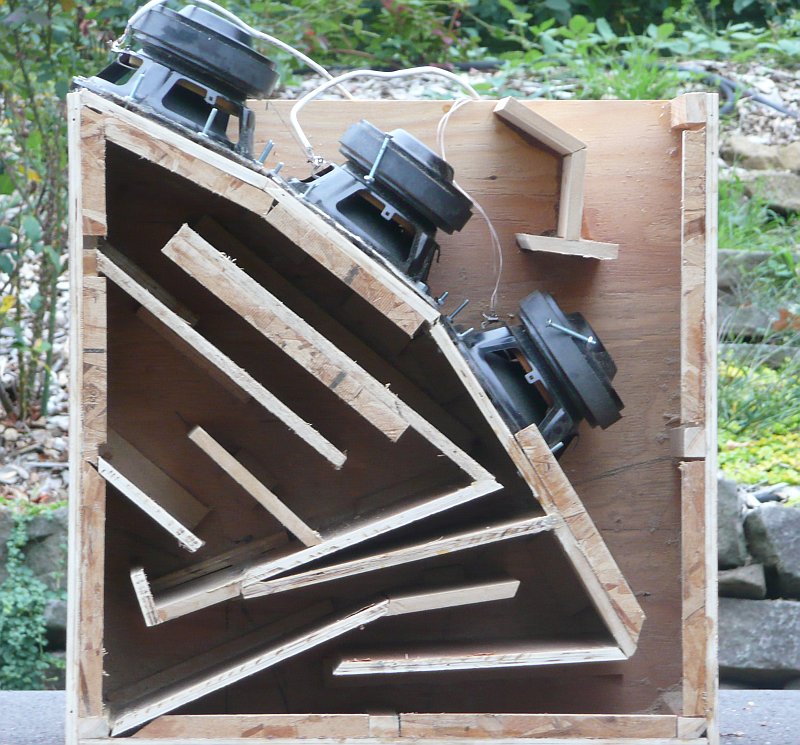
About six weeks ago I built a tapped horn and a front loaded horn, both with the exact same footprint, and with the exact same woofers. THIS is what's required to really A/B the two enclosure types; you need to use the same woofers to do a fair comparison.
In this comparison, the tapped horn was about 12dB more sensitive in the passband. TWELVE DB!!!
That's just a crazy increase in gain.
In a nutshell, you can get the same output in the same foot print with an array of sealed boxes, but nothing comes close to the efficiency of a tapped horn if you DON'T have the luxury of using multiple woofers and lots of power.
The AutoTuba *did* have an increase in efficiency, but it was fairly high in frequency. Below the tuning frequency, the AutoTuba behaved like a simple sealed box.
There IS one big advantage to the front loaded horn, and that is the increase in impedance. This effect is NOT subtle - the 4ohm woofer used in the AutoTuba basically becomes an 8ohm woofer in a front loaded horn. Due to this increase in impedance, your power handling basically doubles (since there's less current in the voice coil.)
Also, I agree with you - neither the AutoTuba nor any of the tapped horn designs are truly horns. They're closer to a transmission line really. I believe this is why cabin gain is in full effect - they're not really horns.
The AutoTuba *did* have an increase in efficiency, but it was fairly high in frequency. Below the tuning frequency, the AutoTuba behaved like a simple sealed box.
+1! Owning a few AT10s myself, I completely agree.
There IS one big advantage to the front loaded horn, and that is the increase in impedance. This effect is NOT subtle - the 4ohm woofer used in the AutoTuba basically becomes an 8ohm woofer in a front loaded horn. Due to this increase in impedance, your power handling basically doubles (since there's less current in the voice coil.)
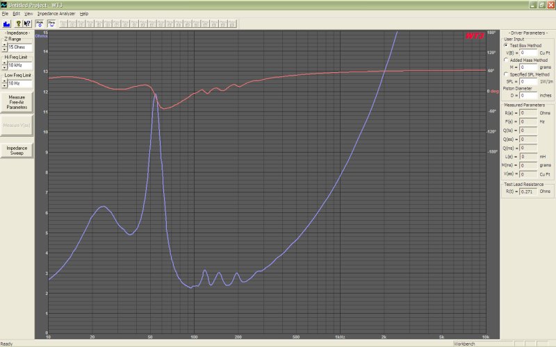
Don't forget about phase angle and it's effect on Power Factor. If one was to look (or calculate) the load as viewed by the amplifier in such as way as described by a technique called Equivalent Peak Dissipation Resistance you'd see that at 108Hz where the phase angle is the most around +63 degrees and 9 Ohms, the load as viewed by the amplifier is still just 4 Ohms. As I recall, but lost the pix, the impedance humps happen in three places for the AT: 40Hz, 80Hz and a small peak somewhere around 120Hz. As the peaks are still just oasis-es in a 4 ohm desert, the rating required for the amplifier is still the minutia.
As I recall, but lost the pix, the impedance humps happen in three places for the AT: 40Hz, 80Hz and a small peak somewhere around 120Hz. As the peaks are still just oasis-es in a 4 ohm desert, the rating required for the amplifier is still the minutia.
Yep.
One of the things that's frustrating about debating box alignments is that people assume that simulations are accurate. And I've found time and time again that simulations will only get you "in the ballpark."
And I've been guilty of this myself - I dismissed tapped horns a couple years ago, because my initial results were poor. What I didn't realize at the time was that there are some simple tricks that can be used to bump up your output.
- When you build a horn, measure the impedance curve. You'll be surprised by what you see - a big bump in impedance. This bump in impedance allows you to use woofers with reaaaaaaaaaly low impedance. For instance, my Triple8 would dip down to 1.2 ohms if it was sealed. Yet my impedance is THREE ohms in a tapped horn. (Low passed at 80hz btw)
The difference between 1.2ohms and 3ohms doesn't seem like a lot, but that's HUGE. That change in impedance lowers the power consumption by over FIFTY percent. Just a crazy improvement.
I wonder if a lot of people build horns without considering the change in impedance? Because doing that really robs your SPL potential. Obviously a 1.2ohm load would blow up most amps, but a 3ohm load is quite manageable. - The other "trick" is to use a MASSIVE flare. When you look at the sims, a big flare doesn't make a huge difference. But in the "real world", the boxes I've built with a substantial flare sound a lot more dynamic, and just plain louder.
I wish I had some measurements or experiments to illustrate the second point. It was one of those things where the improvement was instantly noticeable, and I just stopped doing things "the old way." (IE, I will never build another loudspeaker that doesn't use a substantially flared port.)

Here's a measurement of the impedance of a few subs I have. The purple line is the Triple8 Tapped Horn, which would have a 1.2ohm load if it was sealed.
Bear in mind that an impedance curve for a subwoofer can tell us a lot more than just the resonant frequencies of the alignment. For example, if the impedance at the dips is substantially higher than that predicted by the sims, this could be caused by air leaks between the internal sections of the box.
Bear in mind that an impedance curve for a subwoofer can tell us a lot more than just the resonant frequencies of the alignment. For example, if the impedance at the dips is substantially higher than that predicted by the sims, this could be caused by air leaks between the internal sections of the box.
After building a few tapped horns, I've noticed that more "extreme" designs are less forgiving.
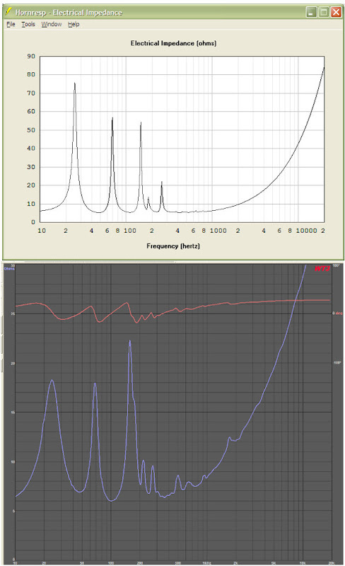
The impedance curve is screwed up. There should be a strong resonance at 35 and 85hz, but there's only one resonance. This "tapped horn" is behaving like a bandpass box. Sorta.
Here's the exact same subwoofer, but I took it apart, and went CRAZY sealing gaps. I literally went up and down the seams with a flashlight, and found about a dozen pinholes. And then I dumped half a tube of liquid nails into all the seams, to insure they're airtight.
Now the resonance is deeper, and more pronounced. But it still doesn't match the prediction.
On the upside, tapped horns seems to be a lot more forgiving of mistuning. For instance, if you mistune a bandpass box, it could create a six dB peak, or it could drop your efficiency by ten dB. When a bandpass box goes wrong, it seems to wrong in a spectacular way.
One the downside, I'm starting to believe that ultra-small tapped horns are VERY unforgiving. For instance, the build quality on my 40hz tapped horn is shoddy at best, and it works just like the prediction. But my 23hz tapped horn, which is half the size, is anything but forgiving.
I am puzzled by a number of thoughts posted and hope someone can help me see the light, please.
1. With a TH with much absorbent and with a signal an octave or two from the resonance, I thought there'd be little difference in output or impedance between enclosure types? In the tuned region, a big difference in output would mean big boomy sound because the rest of the speaker compass is not big?
2. At low frequencies, I take impedance to correspond to motion of the voice coil and with highish impedances meaning loosish, boomish, less controlled motion? Is it true that an "acoustic suspension" is more linear than the restoring forces of the driver's mechanism?
Thanks.
Ben
Last edited:
With a couple more years of building under my belt, I threw together this post to describe what I think one should expect when they sim speakers:
Audio Psychosis • View topic - How to Make You Speakers Sound Better (for Free)
In a nutshell -
Sometimes it can be helpful to use an iterative process. For instance, when doing 3D design I will sometimes start with a design in 2D, get it correct, then export it to a 3D package. The simpler 2D interface makes it possible to 'rough out' and idea before I do the heavy lifting with a more complex program. It's the same way with speakers. It's fun to 'knock out' a simple design in WinISD or the like, but I always fire up hornresp or Akabak before I get ready to make sawdust.
The latter two programs are time consuming, but not as time consuming as a failed or poorly engineered project.
Audio Psychosis • View topic - How to Make You Speakers Sound Better (for Free)
In a nutshell -
- IMHO, WinISD should only be used if you're building a sealed box
- If you're doing anything more complex, Hornresp is the easiest program that will give you accurate results.
- There are so many variables in all other box designs, that using software that ignores these variables is a recipe for disaster. For instance, simply moving the port on the loudspeaker from the front of the box to the back of the box will alter the frequency response.
- Narrow 'blips' in the predicted response will likely be absent or reduced in the real world
- Broad peaks and dips in the response are what we need to look out for
Sometimes it can be helpful to use an iterative process. For instance, when doing 3D design I will sometimes start with a design in 2D, get it correct, then export it to a 3D package. The simpler 2D interface makes it possible to 'rough out' and idea before I do the heavy lifting with a more complex program. It's the same way with speakers. It's fun to 'knock out' a simple design in WinISD or the like, but I always fire up hornresp or Akabak before I get ready to make sawdust.
The latter two programs are time consuming, but not as time consuming as a failed or poorly engineered project.
how do you feel about placement of an enclosure? as in Loading the sub or port?
I feel after reading this entire thread, that if I had done a lil more research I would have had better results? but I was trusting in someone that was suppose to know what they were doing? I was trying to jump into the SQ game without doing the testing myself & well we see the results... for the RECORD Lambros @ Ultra did replace the driver as it seemed that the pole piece was shifted and was affecting the movement of the coil, damaged in shipping / the slugs on the motor were shifted as well. I sent the New sub to my Daughter in Florida and it was installed in a 1cf^3 enclosure with a 500watt mono-block amp and lives on happy and healthy in her Mother-mobile C=
I feel after reading this entire thread, that if I had done a lil more research I would have had better results? but I was trusting in someone that was suppose to know what they were doing? I was trying to jump into the SQ game without doing the testing myself & well we see the results... for the RECORD Lambros @ Ultra did replace the driver as it seemed that the pole piece was shifted and was affecting the movement of the coil, damaged in shipping / the slugs on the motor were shifted as well. I sent the New sub to my Daughter in Florida and it was installed in a 1cf^3 enclosure with a 500watt mono-block amp and lives on happy and healthy in her Mother-mobile C=
What I see in these pictures is a piece-of-junk car audio driver with many design compromises, it's intended to be used only in sealed boxes. A vented box with a single big port in one corner could have produced exactly the same result.
Excursion capability is high, power handling is high, but the design is extremely weak when it comes to handle the cone tilt resulting from uneven acoustical load around the cone and high excursion. That's what produced the rubbing of the voice coil against the pole piece. The driver is not intended to work against a hard and uneven air load (the scenario in most horns).
To make it worse, the spider is very far from the pole piece, so any minor cone tilt results in great deviation of the voice coil from the center. The donut style rubber surround makes it even worse because it does not provide any cone centering effect either.
Such a driver would require at least a symmetrical taped horn or symmetrical ports in a vented box. Anyway, a dual spider driver, or any driver with the spider closer to the pole piece, or just any driver with a cloth surround would be much more reliable in such a tapped horn (for example, almost all pro-audio subs).
Furthermore, one layer of the voice coil got almost completely unwrapped but there are no signs of darkening, so heat was not involved at all. I think it was just due to the lack of quality and quantity in the enamel used to put the magnet wire together and/or improper curing.
Low cost Chinese car-audio subs? No thanks
Spot on.
Another thing that I've noticed in my measurements is that a sealed box mounted in the trunk of a car sees an increase in the impedance curve. My hunch is that the air in the trunk "presses" against the cone, raising impedance and lowering excursion.
Impedance should go down as excursion is reduced. Perhaps you meant the Fb is reduced?
- Status
- This old topic is closed. If you want to reopen this topic, contact a moderator using the "Report Post" button.
- Home
- Loudspeakers
- Subwoofers
- Tapped Horns - Simulation VS Reality