Ok, I take back my words!
I LOVE this place")
So much interesting information that I haven't read it all and two mysteries solved:
1. Tapped horn guide is not right, conical is not two straight sides expanding at a fixes degree. Conical is what google says a ROUND expansion with straight sides (VERY different flare rate!)
2. Stepped horns appears to have sections smaller than 1/4 wavelength.
Biggest SUPRISE is that a stepped horn plays DEEPER than the exponential! But I see no comparison to a horn with a fixed expansion like tapped horns normally have. (What I used to think was "conical" -but it's like a conical shape seen from the side
I LOVE this place
So much interesting information that I haven't read it all and two mysteries solved:
1. Tapped horn guide is not right, conical is not two straight sides expanding at a fixes degree. Conical is what google says a ROUND expansion with straight sides (VERY different flare rate!)
2. Stepped horns appears to have sections smaller than 1/4 wavelength.
Biggest SUPRISE is that a stepped horn plays DEEPER than the exponential! But I see no comparison to a horn with a fixed expansion like tapped horns normally have. (What I used to think was "conical" -but it's like a conical shape seen from the side
1. Tapped horn guide is not right, conical is not two straight sides expanding at a fixes degree. Conical is what google says a ROUND expansion with straight sides (VERY different flare rate!)
Yes, but you can also make a conical horn with flat sides too, it doesn't have to be round. Remember the sentence I bolded in McBean's quote - "Note that a flat-sided symmetrical rectangular horn is only conical when the throat aspect ratio (W1 divided by H1) is the same as the mouth aspect ratio (W2 divided by H2)."
2. Stepped horns appears to have sections smaller than 1/4 wavelength.
That's not necessarily true, it depends entirely on how big the steps are and what the passband is.
In my first 2 step example the steps were acoustically small, Brian said the step effects should start to come into effect at around 60 and 54 hz. But if you look closely at the overlaid frequency response graph I provided you will see that the effect affects the entire subwoofer passband and then some. The differences start at about 20 hz, almost an octave below the low knee and continue all the way up to 2 khz where the response drops below the graph.
I think it would be wiser to forget about the 1/4 wave "rule" entirely and think instead in terms of number of steps. The more steps you have the more closely you can approximate the flare. By the time you get up to 6 steps the response is quite close. Not exactly the same as Danley contends, but still very close. It's actually remarkable that such different flare shapes can produce a result that's so close with only 6 steps. It's only because I'm all about simulation accuracy that I even argue that it's not "exactly the same".
Biggest SUPRISE is that a stepped horn plays DEEPER than the exponential! But I see no comparison to a horn with a fixed expansion like tapped horns normally have. (What I used to think was "conical" -but it's like a conical shape seen from the side
The low knee in the 6 step example is extremely close, definitely within 1 hz. I wouldn't say the stepped horn plays deeper. In the 2 step example the low knee on the stepped version is slightly lower but the frequency response is a mess. Fixing the frequency response by varying the length and csa of the steps would probably bring the two examples closer together both at the low knee and higher in frequency, but it will never be a really good match with only 2 steps.
The point here is that once you get to 6 steps the response is very close. Not exactly the same but very close.
Stepped horns appears to have sections smaller than 1/4 wavelength.
Biggest SUPRISE is that a stepped horn plays DEEPER than the exponential! But I see no comparison to a horn with a fixed expansion like tapped horns normally have. (What I used to think was "conical" -but it's like a conical shape seen from the side
Often quite a bit smaller.
As one goes down in frequency, so ideally goes its flare factor [M or T depending on the paper's author] i.e. becomes increasingly hyperbolic, so bass horns [including 'tapped'] ideally do the same and since a 1/4 WL hyperbolic expansion 'sliced' out of a full size < ~80 Hz horn can look to the eye and more importantly, acoustically, near enough conical [or parabolic the way we build them] over a long distance; it then becomes understandable that 'stepped' plays 'deeper' since acoustically the discontinuity of the bend
GM
Nice work just a guy! Isn't the guy who came up with the THAM15 working on the theory of stepped horns? I swore he took his testing off diyaudio since he wasn't getting any positive support from the community. The support is what I love about this site!
Circlomanen and Martinsson were working on a "discovery" that they referred to as a "quarterwave resonator enhanced tapped pipe". Circlomanen also claimed it was a "revolution in horn design".
An externally hosted image should be here but it was not working when we last tested it.
They got pretty upset when I said "It's a tapped horn using stepped segments instead of a taper. Nothing new here and you can get pretty much identical response by using a regular taper instead."
But the Cyclops CB-18 has been around since at least 2010 and it's the same thing except for s slight flare at the Cyclops mouth.
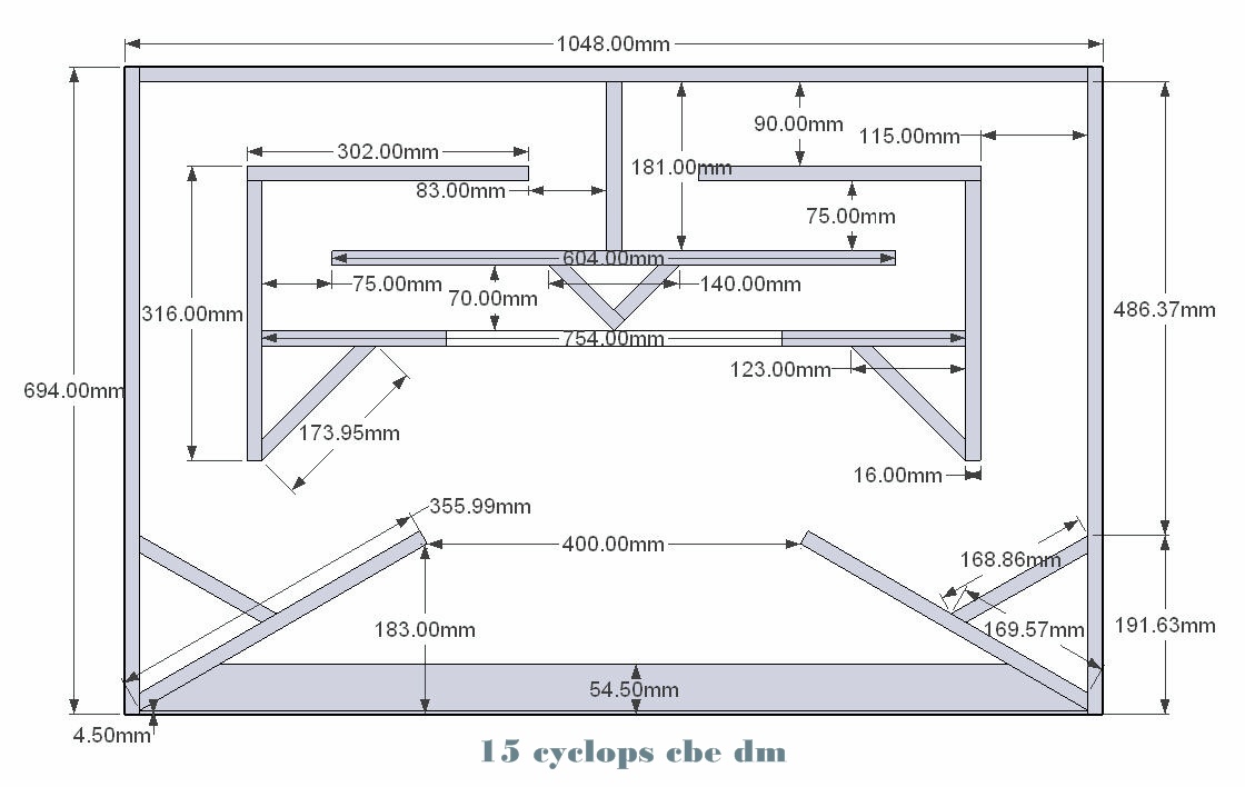
Cyclops details including plans and sim - CB-18 Cyclops
Cyclops discussion dated November 2010 - Extended CB-18 Cyclops - Speakerplans.com Forums - Page 1
The big features of this "new discovery" were the stepped flare, the huge dip right above the passband (which is actually a flaw, not a feature), and the ability to keep a dignified response in heavy power compression (which is actually a good thing but not at all unique to their design).
I also showed earlier in the thread that I could replicate ANY frequency response curve with a different flare shape and even a different alignment (tapped horn vs flh) so the frequency response, the big dip above the passband and the ability to handle heavy power compression gracefully was nothing new.
This is a picture of the huge dip above the passband that they claim is a feature - it's actually a big problem.
An externally hosted image should be here but it was not working when we last tested it.
It's all in this thread, with the "new discovery" part starting here - http://www.diyaudio.com/forums/subw...c-subs-reverse-engineered-26.html#post4508723
To be honest I was a bit blunt with them, but by this time I was getting a bit frustrated because they had presented this very same idea MONTHS before claiming it was the secret inside of Danley's BC (boundary coherent) line of subwoofers. This is so far off the mark it's not even funny, Danley is not using a stepped profile and the BC subs are front loaded horns, not tapped horns. When proven it was NOT similar to Danley's BC series they simply recycled the idea, called it a "new discovery" and presented it again in the same thread.
Additionally they were claiming that the magic in the BC series was a velocity vortex at the mouth that created a virtual extra segment out of thin air and that's why the BC series could play lower than expected. The fact is that the BC series utilize their large frontal area (boundary) to lower the baffle diffraction effect (barn door effect).
There is so much nonsense in that thread I was blunt with them and they got upset and decided to take their "discovery" elsewhere.
And btw, there was PLENTY of support from the community, lots of people encouraged them, check the last few posts of the thread. I was the only one saying it was nothing new, and that was enough for them to get upset and leave.
Last edited:
Just a guy, thanks for your comparison in post 152. I dont know what flare you were approximating but instread of having equidistant segments I think you should try equal expansion. For example S(n+1) = x * S were 1<x<2 and the segment length will be what it becomes. I think you will find an even higher similarity to the original unstepped response this way.
were 1<x<2 and the segment length will be what it becomes. I think you will find an even higher similarity to the original unstepped response this way.Just a guy, thanks for your comparison in post 152. I dont know what flare you were approximating but instread of having equidistant segments I think you should try equal expansion. For example S(n+1) = x * S
It takes about an hour to do the comparison. The sim itself only takes a few minutes but creating the images so you can see what I did takes a lot longer. For each of the 12 segments in the two examples I have to PRINT SCREEN, PASTE into Paint, CROP, COPY, PASTE into another Paint window, MOVE the image to the right spot, then when it's done I have to host the pic and write up the post.
For this reason I'm not going to do a whole bunch of comparisons. So there are two options.
1. You can do it yourself - TL.app is super simple to use and the sim only takes a few minutes.
2. I can do one more comparison, but I'm only doing one more. Brian wanted me to do a comparison on a known design, one of the THAMs I think. And I'm not even sure what you are suggesting I should compare.
SO if you guys want one more comparison there needs to be a consensus on what you want to see. Then I need ALL the horn details - rear chamber volume (if it's a front loaded horn), driver specs (it would be cool if it used the B&C 18tbw since I've got the specs loaded already), and I need detailed info on the segments. The horn that you want to be compared MUST be split into PAR segments (so I can easily convert the expanding segment into a stepped counterpart and then easily compare volumes of each and make sure the stepped equivalent is equal volume to the expanding counterpart), I would suggest 6 segments but that's up to you (no more than 6 though) and I need the beginning and end cross sectional area of each segment as well as the lengths.
Last edited:
Yes, and it's very easy and intuitive to use. You'll need to Help file to figure out how to do some stuff but most of it is very easy to figure out on your own. Just don't try to sim tapped horns with it, last time I tried the tapped feature gave terribly incorrect results and I don't think it was ever fixed.
First test. The help-file was good and the program is rather intuitive after the
initial head-scratch...
I simulated a stepped FLH using B&C 15TBW100 & I've simulated in hornresp
using exp. and made a CAD-sketch of it. Anyhow, the TL.app-response* and
hornresp response is very similar in the unstepped version. I used a 5 step
expansion and overlayed the curves. The stepped horn appears to be
slightly larger when looking at the freq. response. A bit lower f3, deeper
suck-out between the peaks. Over all, these differenses I concider to be
very small, within a dB. I might reduce the box size by some % and se if it
will be even more similar to the true expansion but we'll start with these
results:
Black is stepped, gray is continuous* (though stepped par-expansion, i.e.
what would be possible to build) Note that the 20 dB scale enhance
differences. A different scale like hornresp 50 dB would flatten out the
differences quite effectivly.

Box, hwd 106,5 x 43,6 x 67,9 cm

I'll stick to hornresp and just confirm my designs with the TL.app, think this is
the most time-efficient way to design and optimize enclosures if not using Akabak.
Thanks again just a guy for showing me to this simulation tool!
/Petter
initial head-scratch...
I simulated a stepped FLH using B&C 15TBW100 & I've simulated in hornresp
using exp. and made a CAD-sketch of it. Anyhow, the TL.app-response* and
hornresp response is very similar in the unstepped version. I used a 5 step
expansion and overlayed the curves. The stepped horn appears to be
slightly larger when looking at the freq. response. A bit lower f3, deeper
suck-out between the peaks. Over all, these differenses I concider to be
very small, within a dB. I might reduce the box size by some % and se if it
will be even more similar to the true expansion but we'll start with these
results:
Black is stepped, gray is continuous* (though stepped par-expansion, i.e.
what would be possible to build) Note that the 20 dB scale enhance
differences. A different scale like hornresp 50 dB would flatten out the
differences quite effectivly.
Box, hwd 106,5 x 43,6 x 67,9 cm
I'll stick to hornresp and just confirm my designs with the TL.app, think this is
the most time-efficient way to design and optimize enclosures if not using Akabak.
Thanks again just a guy for showing me to this simulation tool!
/Petter
Box, hwd 106,5 x 43,6 x 67,9 cm
Interesting results. What's the length of the longest section?
First test. The help-file was good and the program is rather intuitive after the
initial head-scratch...
I told you it was easy to learn. I wrote a large part of the help file to help the author of the program. I was glad to donate the time to help out for such a great little program.
Anyhow, the TL.app-response* and
hornresp response is very similar in the unstepped version.
Yes, the results are very very close to the results you get with Hornresp. i did a couple of comparisons with front loaded horns to judge whether or not to trust this program initially.
The problem is the tapped part of the program. The results I got very very badly off compared to Hornresp and as far as I know it was never fixed, so don't sim any tapped designs until/unless you do a Hornresp comparison first to make sure it works properly.
Thanks again just a guy for showing me to this simulation tool!
/Petter
No problem. Nice work. Did you check the segment volumes to make sure they were all exactly correct? When using PAR segments it's pretty easy to convert from expanding to stepped but I usually like to show all my work just in case. Also it's interesting to see the schematic drawing that the program provides.
Anyway, like I said, stepped is close but not the same.
How did you do the overlay? This is a very handy skill that I'd like to be able to do.
Last edited:
Brian,
I'll come up with a complete drawing later in a new thread to avoid spamming
this one whith my design although the segments have the following length. I
just recalculated them (used an approximation before, now the segment
volumes are exactly the same as supposed. The approximation gave a minor
error but it was good for evaluation though). The new theoretically correct
outer dimensions are 107.0 x 43.6 x 68.1. Matches the hornresp schematic
to all decimals.
Segment 1-5:
41.8 cm (40 + 1.8)
41.8 cm (40 + 1.8)
41.8 cm (40 + 1.8)
64.7 cm
66.3 cm
I have calculated the horn path length according to the summed segment
lengths. I know you're supposed to do a mid-way in the turns but this makes
it so much easier and I doubt the differences are gigantic...I am making a
spread sheet where you insert throat and mouth area, length and inner
width of the cabinet. Then you adjust the first segment length until the horn
length match the theoretical horn length. You will then get a drawing right in
the excel sheet. It can not be simplier, only straight cuts.

Just a guy,
Yes, the segments were almost the same, the volume of the stepped horn
was in total 0.91 % smaller than the theoretic volume. I'm away from the
computer so I can't make a new simulation but I doubt the differens are
very large. Anyhow, this forced me to spend two hours to convert the
approximation to an exact model, which is good in the end though...
I did not find an overlay-tool in the program itself, so I took a copy (right
click) of the graph and pasted it in excel. I forced it to the upper left corner
in the spread sheet. Then I made a new simulation and copied that too.
Pasted it in the same excel sheet but to the side of the already pasted
graph. Then I tok a new grip of the newly pasted graph and forced that
too to the upper left corner. It will the auto align. Do not drop it! The graph
underneath will appear translucent when the second graph is held over it.
Then you take the left hand and make a print screen. Post in paint or other
program and cut the part of interest and save. Voila
I'll come up with a complete drawing later in a new thread to avoid spamming
this one whith my design although the segments have the following length. I
just recalculated them (used an approximation before, now the segment
volumes are exactly the same as supposed. The approximation gave a minor
error but it was good for evaluation though). The new theoretically correct
outer dimensions are 107.0 x 43.6 x 68.1. Matches the hornresp schematic
to all decimals.
Segment 1-5:
41.8 cm (40 + 1.8)
41.8 cm (40 + 1.8)
41.8 cm (40 + 1.8)
64.7 cm
66.3 cm
I have calculated the horn path length according to the summed segment
lengths. I know you're supposed to do a mid-way in the turns but this makes
it so much easier and I doubt the differences are gigantic...I am making a
spread sheet where you insert throat and mouth area, length and inner
width of the cabinet. Then you adjust the first segment length until the horn
length match the theoretical horn length. You will then get a drawing right in
the excel sheet. It can not be simplier, only straight cuts.
Just a guy,
Yes, the segments were almost the same, the volume of the stepped horn
was in total 0.91 % smaller than the theoretic volume. I'm away from the
computer so I can't make a new simulation but I doubt the differens are
very large. Anyhow, this forced me to spend two hours to convert the
approximation to an exact model, which is good in the end though...
I did not find an overlay-tool in the program itself, so I took a copy (right
click) of the graph and pasted it in excel. I forced it to the upper left corner
in the spread sheet. Then I made a new simulation and copied that too.
Pasted it in the same excel sheet but to the side of the already pasted
graph. Then I tok a new grip of the newly pasted graph and forced that
too to the upper left corner. It will the auto align. Do not drop it! The graph
underneath will appear translucent when the second graph is held over it.
Then you take the left hand and make a print screen. Post in paint or other
program and cut the part of interest and save. Voila
Segment 1-5:
41.8 cm (40 + 1.8)
41.8 cm (40 + 1.8)
41.8 cm (40 + 1.8)
64.7 cm
66.3 cm
Given s=345 m/s, the 1/4W frequencies for those segments are 206 Hz, 133 Hz and 130 Hz.
From your graph, you've got a 1dB variation that's centered around 120~130 Hz, and a larger 2dB variation centered around 200 Hz.
Gents, I rest my case. Keep those segments less than 1/4W for your horn's target passband and you should be safe using a HornResp sim with a smooth flare to emulate your stepped horn
. Any little 0.5dB difference here and there, forget about it - you've going to see much greater variation due to things like HornResp not taking losses into consideration.Brian, thanks for the clarification. I dont see it as a right or wrong thing...I'm
just lazy but like to do compromises that eases manufacturing but not
influence the end result significantly. It is a lot more conveniant to cut
and assembly a stepped horn. Bracing is also a lot easier. Hopefully this
will revolutionize the way people build their horns hereforth and that the
threshold for new horn-DIYers is reduced = more build threads.
It would be fun in anyone made a stepped and correct horn of the same flare
and size. Things like turbulence and others are difficult to simulate.
just lazy but like to do compromises that eases manufacturing but not
influence the end result significantly. It is a lot more conveniant to cut
and assembly a stepped horn. Bracing is also a lot easier. Hopefully this
will revolutionize the way people build their horns hereforth and that the
threshold for new horn-DIYers is reduced = more build threads
. It would be fun in anyone made a stepped and correct horn of the same flare
and size. Things like turbulence and others are difficult to simulate.
Okej, here's the final call...got to borrow a computer.
5 segments having equal start and end area of each segment in both horns.
The gray curve has par-segments and the black has exp-segments. Thus
the par-horn is slightly larger which is why the low freq. is higher in
sensitivity. I'm pretty sure the graphs would overlay perfectly if I made the
effort to do the volume correction. Anyhow, the similarity is obvious.

Next simulation, stepped vs exp.
Gray is a five segment exponential-segment horn which approximates an
exponential curve, i.e. equal to a 1-segment exp. horn. The black is a five
segment stepped horn of the same volume and length. Less than a dB in
difference at the frequenses of usage, i.e. below ~170 Hz. The stepped
horn has higher sensitivity at lower freq. bot lower at higher freq. than the
pure exponential horn.

5 segments having equal start and end area of each segment in both horns.
The gray curve has par-segments and the black has exp-segments. Thus
the par-horn is slightly larger which is why the low freq. is higher in
sensitivity. I'm pretty sure the graphs would overlay perfectly if I made the
effort to do the volume correction. Anyhow, the similarity is obvious.
Next simulation, stepped vs exp.
Gray is a five segment exponential-segment horn which approximates an
exponential curve, i.e. equal to a 1-segment exp. horn. The black is a five
segment stepped horn of the same volume and length. Less than a dB in
difference at the frequenses of usage, i.e. below ~170 Hz. The stepped
horn has higher sensitivity at lower freq. bot lower at higher freq. than the
pure exponential horn.
Given s=345 m/s, the 1/4W frequencies for those segments are 206 Hz, 133 Hz and 130 Hz.
From your graph, you've got a 1dB variation that's centered around 120~130 Hz, and a larger 2dB variation centered around 200 Hz.
Gents, I rest my case. Keep those segments less than 1/4W for your horn's target passband and you should be safe using a HornResp sim with a smooth flare to emulate your stepped horn
I guess we interpret things differently. I see very close to 1 db difference at the low knee AND the low knee is shifted a couple of hz. As I said, this affects things WAY below the 1/4 wavelength of the stepped segments. Correctly predicting the low knee is arguably one of the most important parts of a design. And then starting at 80 hz and up the correlation is terrible with up to 3 db differences and most of the peaks don't line up at the same frequencies. This is a 40 hz horn, if it was a 20 hz horn a lot of that garbage in the higher frequencies would be right in the passband.
This is not a good correlation at all if you value accurate simulation IMO and if you want to build it stepped you should simulate it as stepped.
Like I said, close but not the same thing.
Variations from things Hornresp doesn't take into account like losses are a totally separate issue and not an excuse to be sloppy with simulation. Stuff like this is EXACTLY why some people don't trust simulators and claim they are not accurate.
Last edited:
- Status
- This old topic is closed. If you want to reopen this topic, contact a moderator using the "Report Post" button.
- Home
- Loudspeakers
- Subwoofers
- Tapped Horn TH-121 build