I don't disagree with you Greg
You are completly correct. It is to short. I did some impedance measurements. The kids got all excited to help out and voila I have some actual measurements of the electricals. The box does have the double peak that is simmed in hornresponse. But that being said there are a lot of reasons why the second bump is not so prominent. I got a passband from 35hz to 85hz not to bad. Will see what the acoustical measurements bring me.
For completeness there is the driver with out any loading. ( I have a couple on hand right now other than the ones in the box ) And I have to find the little program from Neutrik that produces wave files of test frequencies so I can make a simple test disk to load into the car and sit there with meter in hand and graph paper at the ready to plot the response. Crude but it's the way I did it 20 years ago and it still works. Lost all the programs on the computer and it's not worth the setup time right now.
Raw Driver
Driver in Mouth of Box
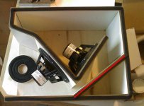
Driver orientation
Single driver at the mouth of box
Both drivers in box
So there we go. Now there are some things to discuss. One question is the lower second peak. The sealing will be checked out to determine if that is the problem. Thats my guess.
Mark
We'll have to agree to disagree that it's a TH
what I see is what you ~simmed, a reverse tapered TL mass loading a very short expanding 'horn stub' vent similar to at least one of the '50s era simple corner horns, so even with a suitable corner, 'horn-like' seems the most appropriate description
You are completly correct. It is to short. I did some impedance measurements. The kids got all excited to help out and voila I have some actual measurements of the electricals. The box does have the double peak that is simmed in hornresponse. But that being said there are a lot of reasons why the second bump is not so prominent. I got a passband from 35hz to 85hz not to bad. Will see what the acoustical measurements bring me.
For completeness there is the driver with out any loading. ( I have a couple on hand right now other than the ones in the box ) And I have to find the little program from Neutrik that produces wave files of test frequencies so I can make a simple test disk to load into the car and sit there with meter in hand and graph paper at the ready to plot the response. Crude but it's the way I did it 20 years ago and it still works. Lost all the programs on the computer and it's not worth the setup time right now.
An externally hosted image should be here but it was not working when we last tested it.
Raw Driver
An externally hosted image should be here but it was not working when we last tested it.
Driver in Mouth of Box
An externally hosted image should be here but it was not working when we last tested it.
Driver orientation
An externally hosted image should be here but it was not working when we last tested it.
Single driver at the mouth of box
An externally hosted image should be here but it was not working when we last tested it.
Both drivers in box
So there we go. Now there are some things to discuss. One question is the lower second peak. The sealing will be checked out to determine if that is the problem. Thats my guess.
Mark
Quick efficiency test
Ok here it is 1 watt or 2.00 volts into 4 ohms. The SPL meter is 1 meter away from the box mouth in the car so this is definitly 1/8th space measurement. But were getting 108db/watt. So now I have some more thinnin to do. Is this not a artifact of proper loading?
Comments would be welcome
Mark
P.S.
Hello Henkjan. If you take this out you kill the response. I'll post the Hornresponse input data below and hope GM and others will hammer away at it.
Ok here it is 1 watt or 2.00 volts into 4 ohms. The SPL meter is 1 meter away from the box mouth in the car so this is definitly 1/8th space measurement. But were getting 108db/watt. So now I have some more thinnin to do. Is this not a artifact of proper loading?
Comments would be welcome
Mark
An externally hosted image should be here but it was not working when we last tested it.
P.S.
what would happen to the respons if you took the part out that I marked red in the photo?
Hello Henkjan. If you take this out you kill the response. I'll post the Hornresponse input data below and hope GM and others will hammer away at it.
An externally hosted image should be here but it was not working when we last tested it.
Re: Subjective impressions
That performance can also be achieved with Infinite Baffle, closed box, and aperiodic variants in an automobile. I've never heard it done with a vented enclosure in a car. Start by looking at the positions and space available in the car and work towards a driver choice from there. Which you've done nicely.
IME, one note bass results from one-note music, poor tuning/EQ/integration, and a misunderstanding of listening as much as poor enclosure design. Too often it's all four. Thus my exodus from the car audio business years ago.
Thanks for posting your idea and experiences.
mwmkravchenko said:
The tapped horn has the characteristics that make most horn systems the holy grail of low end. If there is no low end there you don't get any. If there is you do. It's the death of one note bass. It takes a bit of getting used to. We all listen to sub systems that trade clean output for distorted output the lower we go in frequency.
Mark
That performance can also be achieved with Infinite Baffle, closed box, and aperiodic variants in an automobile. I've never heard it done with a vented enclosure in a car. Start by looking at the positions and space available in the car and work towards a driver choice from there. Which you've done nicely.
IME, one note bass results from one-note music, poor tuning/EQ/integration, and a misunderstanding of listening as much as poor enclosure design. Too often it's all four. Thus my exodus from the car audio business years ago.
Thanks for posting your idea and experiences.
The inner driver is acoustically short circuited in the bottom octaves and should not add substantial output in practice. In an optimum setup a second driver should add 6dB while drawing only 3dB more power.
The outer driver sees a 6th-order bandpass with the lower tuning around 63Hz and the higher one somewhere below 200Hz.
It would require a much longer path length to be considered a transmission line or tapped horn and much higher cross-sectional area to provide smooth horn loading to the drivers (uniform reduction of cone displacement in the passband, and not just peaky reduction at some frequencies).
...It would require a much longer path length to be considered a transmission line or tapped horn …
Agree, and there is more to worry about: like the driver parameters used for input of the simulation and that the simulation schematic doesn't correspond to the implemented box :
See picture 1(2) and 2(2) that suggests the both simulated drivers rear/front sides are close to each other and not separated as shown in the real world pictures.
b
1(2)
Attachments
Hi EVA, Bjono
Eva said:
The outer driver sees a 6th-order bandpass with the lower tuning around 63Hz and the higher one somewhere below 200Hz.
If what you are saying is correct explain the two impedance peaks which in any box show the resonant frequency of the box design.
Let me make one thing perfectly clear. I don't consider this a perfect horn anything. I whole heartedly agree that it is to short to be horn loaded. But my measurements and ears are telling me something is working. I don't believe in fair dust engineering. I've been at this for 20 years profesionally and semi-profesionally. But there is an interesting problem. Lets break this down a bit. If I'm correct in this assumption.
1 driver = 87 db
2 drivers=90 db
electrical gain in efficiency by halving the input impedance + 3db
1/8th space testing environment +6 db
total 99db/watt
I measured 106db. And I stand by the measurement it was done carefully at exactly 1 meter and 2 volts input at a frequency within the acurate bandwidth of a cheap meter. ( 45hz ) The SPL meter has a new battery, the weighting was set on C and the response set to slow averaging as I tried to show in the picture. The SPL meter was set at 110db range. That loudness level would be at the 0 position.
So where do the extra 7 db of gain come from?
If the drivers were on an h baffle we would not get that amount of gain. A bandpass can create this amount of gain under optimum conditions. But there is no sealed chamber and no resonator. I'm not sugesting some kind of discovery here by any means. But I am asking other people to give constructive criticisim.
The raw driver data is for a driver in the free air. It's efficiency is almost 87db/watt. The data screens that Bjorno calls into question are the dual drivers parameters measured in the funny little box. They are different from free air loading as a result of being in the box. Quite simple really. The design input window and the schematic are done from measured specs before placing the drivers into the box. No vodoo there. I think I miss labeled them or Bjorno misunderstood what I labeled. There has to be a difference in driver specs once they are in a cabinet or even a large baffle.
Eva's comment on the second driver is interesting and I will investigate it. It may be incorrect as I am getting 106 db ( not 108) per watt into 4 ohms. The measurement was taken at 45hz. So that kind of makes me think that both drivers are still summing output even at this frequency. The lower point of resonance simulated and measured are close and at or about 35 hz. The second driver is as close to the position specified in the schematic as is physically possible. And the first driver is exactly as simulated. So I do think that the design is close to the simulation
Mark
P.S. Just great the sharks are circling and I'm wearing tuna flavoured shorts!
One more little tidbit to chew on
Path length to short?
The actual path length is 40 " or 1016 mm
This is the actual 1/4 WL of 35hz.
That is also the low end resonance measured electrically and more or less verified imperically today. I listened to plenty of 16' low C notes on the way home from dropping off my kids. The box can almost pull them off without straining to hard. And that is about 32 to 34hz on most pipe organs.
Mark
Path length from the back to the front of the inner driver is like 25cm, and 45cm for the outer driver.
Two or three impedance peaks are characteristic of bandpass enclosures too. In a horn you would see more peaks.
In any case, the last valley happens at 63Hz and this determines where bandpass or horn loading ends. In general, LF impedance plots are made of a big peak from driver resonance with dips in it reflecting enclosure or horn resonant modes.
In the following PDF you can see what the impedance plot of a true 20Hz tapped horn looks like. There is probably another peak below 20Hz not shown in the plot:
www.danleysoundlabs.com/pdf/TH 221 spec sheet.pdf
Hi Eva
I measured the inner driver alone mounted in the horn. You are right in that it does decouple from the driver in the mouth. You just picked the wrong end of the frequency response.
Of note is the little bit higher resonant point. The other thing to point out is the lack of the secondary peak. But when wired in reverse I get exactly the same peak as the driver in the mouth. The combined impedance graph has been posted.
The drivers are being effected by the air load presented by the coupling chamber. The response is shaped by the narow slot at about 1 cm wide. In simulations chaning this greatly effected the response.
Now I have to ask again where are the extra dbs coming from? The horn length is the distance from the begining of the coupling chamber to the end of the mouth. It is from this point that the first driver that is situated in the mouth of the enclosure is loading the box. That is a standard way of length measurement in a horn. The second woofer tapps the box at 1/4 of the way out or there abouts. This is not a perfect position for the driver. It is a practical one. Remember that this is an exercise in smallest volume biggest clean sound. The first design posted is a true horn with a falling response. I will build that one when I have thoroughly worked out what this little moster is doing. This box is not designed specifically to mirror a falling response in a car. But it does have by default a 12db slope/octave at the low end. It should be noted that driving a horn below it's resonant point on the low end is a good recipe for a quick death just as it is with a vented box. The cones flap and you don't get much sound.
Mark
I measured the inner driver alone mounted in the horn. You are right in that it does decouple from the driver in the mouth. You just picked the wrong end of the frequency response.
An externally hosted image should be here but it was not working when we last tested it.
Of note is the little bit higher resonant point. The other thing to point out is the lack of the secondary peak. But when wired in reverse I get exactly the same peak as the driver in the mouth. The combined impedance graph has been posted.
The drivers are being effected by the air load presented by the coupling chamber. The response is shaped by the narow slot at about 1 cm wide. In simulations chaning this greatly effected the response.
Now I have to ask again where are the extra dbs coming from? The horn length is the distance from the begining of the coupling chamber to the end of the mouth. It is from this point that the first driver that is situated in the mouth of the enclosure is loading the box. That is a standard way of length measurement in a horn. The second woofer tapps the box at 1/4 of the way out or there abouts. This is not a perfect position for the driver. It is a practical one. Remember that this is an exercise in smallest volume biggest clean sound. The first design posted is a true horn with a falling response. I will build that one when I have thoroughly worked out what this little moster is doing. This box is not designed specifically to mirror a falling response in a car. But it does have by default a 12db slope/octave at the low end. It should be noted that driving a horn below it's resonant point on the low end is a good recipe for a quick death just as it is with a vented box. The cones flap and you don't get much sound.
Mark
Doin a little more thinnin
Does anybody who has been peeking at this thread have any experience with a H baffle? If you look at the so-called fold it could work out as a bit of an H-baffle. Just a thought.
Second fishing expedition is this. One gentleman pointed out that the drivers load the box from three sides. As this is true the radiation gained from the surfaces that actually drive the enclosed box volume summ and what do we get with this? Higher SPL???
This design is not a true acoustical impedance transformer or horn. As Eva pointed out there maybe a very peaked response on the output. That I have not verified with accurate measurements. I'm digging up my old program suite and hoppong that I still have some of my assorted toys to do this fairly quickly.
Mark
Thinnin is what happens when you sand cabinet parts all morning and your mind starts a wondering.
The good the bad and the ugly
I'm still not unhappy!
Here is the raw data:
So to put a marketing perpective on it we have =/- 3db from 40 to 100 hz. There is a nasty resonance in the car at these levels between 70hz and 85 hz. With some judicous use of a loudness contour the low end is decent down to 35 hz. So this little unhorn is doing what it was designed to do. Hell if I know what to call this little thing. It works as a narrow bandwidth subwoofer. And that is exactly what most subwoofers are asked to do. It is very efficient at 106 db/watt into 4 ohms and can stand a bit of eq that will tame the problems. Any sub measured to that level of precision in a car will wobble up and down in a similar fashion. So this is more than respectable for two 6.5" drivers in an enclosure that we don't know what to call. So I present the unhorn.
Mark
Time to get a movin for the plans you think?
I'm still not unhappy!
Here is the raw data:
An externally hosted image should be here but it was not working when we last tested it.
So to put a marketing perpective on it we have =/- 3db from 40 to 100 hz. There is a nasty resonance in the car at these levels between 70hz and 85 hz. With some judicous use of a loudness contour the low end is decent down to 35 hz. So this little unhorn is doing what it was designed to do. Hell if I know what to call this little thing. It works as a narrow bandwidth subwoofer. And that is exactly what most subwoofers are asked to do. It is very efficient at 106 db/watt into 4 ohms and can stand a bit of eq that will tame the problems. Any sub measured to that level of precision in a car will wobble up and down in a similar fashion. So this is more than respectable for two 6.5" drivers in an enclosure that we don't know what to call. So I present the unhorn.
Mark
Time to get a movin for the plans you think?
Measure where it is to be used
Hello Eva
I designed this box for the car environment. All of it's design compromises are made so that it functions as designed in a car environment.
If you are informed enough to ask the question of why I did not measure it out in a half space environment then you will know that automatically without any corner reinforcement the efficiency will drop by 6db maybe even 8db. The low end will suffer to the tune of rapidly rolling off below 60hz instead of 30hz. So a loss of an octave of output.
This enclosure is a carefull dance between size and low frequency extension. I have carefully documented it. And to the credit of David McBean whose sofware helped me design this I was able to come up with a wierd little hybrid unhorn enclosure that gets some of the gain a proper horn loading would generate. The no free lunch clause is that it works only in a small acoustical space. It operates in a very narrow bandwidth. But a subwoofer usually operates over narrow bandwidth of 1 1/2 to 2 octaves anyway. 80-40 is one octave 40 to 20 is the second octave. This little box pulls off 1 1/2 octaves. Gives you a tremendous SPL capability and has a rather clean character of reproduction.
But the theme tapped horn for car maybe telling where it was intended to be used. Therefore that is where I measured it.
Mark
I have experience with cabin gain effects, I have done several custom subs for cars like yours during the past 10 years, usually with very limited space available. 6th-order bandpass always seemed to be the best approach because it provides high efficiency with low cone displacement.
But you can't compare efficiencies inside a car unless it's always the same car. 106dB/W may not be good at all for your cabin gain. Who knows if with some improvements you could be getting 110dB/W.
Of course, the frequency response will change in half space, but at least this allows to compare efficiencies to well known figures. If you get well over 90dB/W at 60-80Hz in half space, you can consider it efficient.
My half space target frequency respnse was usually maximum efficiency betwen 80Hz and 150Hz, falling 3dB or so to 60Hz, then another 12dB to 30Hz, then falling at 24dB/oct below that. In some cases I was able to approach 100dB/W half space at 80Hz.
Then cabin gain flattens it nicely...
Fair enough Eva.
I apologise because I thought you were only trying to poke holes in the design.
I have seen the work you put into your electrical engineering projects and should take your opinion a little more seriously.
A bandpass enclosure will get you a maximum gain in efficiency of 7db over an octave and a half maybe two at most. asked to play loud out of the passband you have the food processor effect. Shredded woofers. I don't build that kind of box for anyone as kids generally destroy their woofers faster than they can open the box and change them out. Bye bye woofers. You are a brave man Eva.
As for increasing efficiency I played with the simm for a couple of days. You can only trade bandwidth for efficiency. No free lunch on this one. With greater efficiency came lower bandwidth. What I ended up making was what I felt made the best compromise.
For the sake of fairness I will test it outside ground plane with this caveat. I only have so much wire comming out of the car. So it will not be half space as in against a wall floor juction but a true ground plane with no boundary reinforcement. So what ever I come up with will need to be bumped up 3 db to reflect a floor wall boundary effect.
Mark
P.S. A sealed box version with two drivers maybe a simple test to see the cabin gain on an equal footing. Actually that could be easily modeled in a number of programs that I should install. Will be back on this one.
P.P.S. Eva don't you sleep sometimes? What time is it over there?
I think that your box design does not correlate well to the hornresp model, it could probably be improved by extending the first section, that's why I ask you to measure "unbiased" efficiency, and compare to hornresp results (half space too). If it's close or better, then the box layout is ok. I bet you will get a few dB less than predicted.
I didn't build one note boxes, tunings were well spaced, typically around 37Hz and 100Hz for minimum overall cone displacement, with moderate resonant Q. Some of my layouts were not very different from yours. The cabin and the proximity of surfaces inside the car detunes the "ports" to the low side, usually requiring fromt chambers just like yours, without a port or even a wall sometimes. We only had problems with one crazy kid blowing speakers until we found something with a big enough voice coil.
btw: I have strange sleep time (it's 5 AM or so). My current main customer is overseas and is probably having dinner now.
- Status
- This old topic is closed. If you want to reopen this topic, contact a moderator using the "Report Post" button.
- Home
- Loudspeakers
- Subwoofers
- Tapped Horn For Car