Sims of this speaker in AkAbak
I am just learning how to simulate MLTL's using AkAbak (Acoustic Abacus software). With the generous help of Don Hills, I have been able to cobble together what I think is a quad driver bipole MLTL that is built here. The design was based on the Accidental MLTL - so there was no simulation other than to assume a standard bass reflex for the port tuning.
The dimensions used were as built: 5 in wide x 8.5 in deep x 40 in Long with drivers at the top 1/3 position and the vent situated at the bottom firing onto the floor. The vent sits about 4.25 in above the floor.
What I am finding out from using AkAbak is that it is very versatile and powerful for trying out new configuratins with multiple drivers that can be arbitrarily pointed. The simulation assumes a single back wall and a floor, otherwise radiates into infinite free space. The "measurement" is at 1 meter with 2.83 volts driving the speakers.
The simulation so far does not have any damping effects provided by the stuffing so you will see peaks and valleys - ignore them and smooth them out mentally. I am working on that...
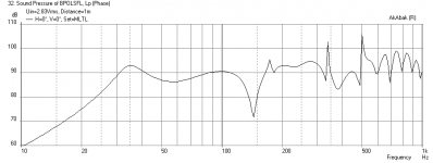
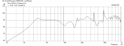
What is very informative to see is the effect of placement of a bipole away from a wall. At 2 ft away (first image below), the response is terribly dipped but at 5 ft away (second image below), the bass response is fairly flat. As we can see it reaches down to about 53 Hz as expected even though the tuning was for a 65 Hz bass reflex box. So there is about a 12 Hz deeper bass extension due to the "Accidental" MLTL effect.
I am just learning how to simulate MLTL's using AkAbak (Acoustic Abacus software). With the generous help of Don Hills, I have been able to cobble together what I think is a quad driver bipole MLTL that is built here. The design was based on the Accidental MLTL - so there was no simulation other than to assume a standard bass reflex for the port tuning.
The dimensions used were as built: 5 in wide x 8.5 in deep x 40 in Long with drivers at the top 1/3 position and the vent situated at the bottom firing onto the floor. The vent sits about 4.25 in above the floor.
What I am finding out from using AkAbak is that it is very versatile and powerful for trying out new configuratins with multiple drivers that can be arbitrarily pointed. The simulation assumes a single back wall and a floor, otherwise radiates into infinite free space. The "measurement" is at 1 meter with 2.83 volts driving the speakers.
The simulation so far does not have any damping effects provided by the stuffing so you will see peaks and valleys - ignore them and smooth them out mentally. I am working on that...
What is very informative to see is the effect of placement of a bipole away from a wall. At 2 ft away (first image below), the response is terribly dipped but at 5 ft away (second image below), the bass response is fairly flat. As we can see it reaches down to about 53 Hz as expected even though the tuning was for a 65 Hz bass reflex box. So there is about a 12 Hz deeper bass extension due to the "Accidental" MLTL effect.
Attachments
X,
I usually pull them farther out than that to listen but thats where they sit when not in use. Two dogs + two kids= knocked over towers.
I did a quick sketch on the 6.5 silver flute bipole but havent scanned it in to my computer yet. I'll try and get that done tomorrow and post it in this thread.
I usually pull them farther out than that to listen but thats where they sit when not in use. Two dogs + two kids= knocked over towers.
I did a quick sketch on the 6.5 silver flute bipole but havent scanned it in to my computer yet. I'll try and get that done tomorrow and post it in this thread.
X they do sound better pulled that far away from the wall. I did get a funny look from the Mrs. when she walked in but she sat and listened and also agreed. Thanks for the tip.
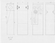
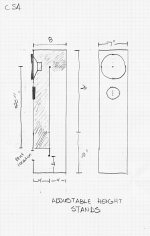
Here's the quick drawing for the 6.5 silver flutes. I was trying to get the folds plus a stand in the 48" kind of like the tangband box so I can have the port firing down. Maybe an internal square port and have the bottom off the ground 4"
Just thinking out loud
Here's the quick drawing for the 6.5 silver flutes. I was trying to get the folds plus a stand in the 48" kind of like the tangband box so I can have the port firing down. Maybe an internal square port and have the bottom off the ground 4"
Just thinking out loud
Attachments
X they do sound better pulled that far away from the wall. I did get a funny look from the Mrs. when she walked in but she sat and listened and also agreed. Thanks for the tip.
Here's the quick drawing for the 6.5 silver flutes. I was trying to get the folds plus a stand in the 48" kind of like the tangband box so I can have the port firing down. Maybe an internal square port and have the bottom off the ground 4"
Just thinking out loud
Ryan,
OK, so the AkAbak simulation seems to be holding some "truth". Thanks for the feedback on the positioning as that is something that would have been total guesswork without the model. Don Hills will be happy to hear that his MLTL script that he gave me and I modded to be a bipole with 4 drivers is working out well.
For your Silver Flutes, I think I can make a similar cabinet if you want to keep it at 48 in. If I make a fold I will try to keep it as simple as possible. What is your preference for the driver height? I can play around with that as a parameter as it sometimes makes a big difference.
Silver Flutes Bipole MLTL Design
Ryan,
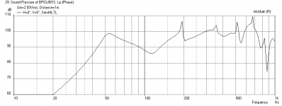
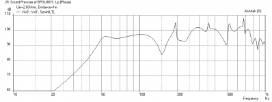
The Silver Flutes are low Qts drivers and I am having a harder time controlling them to make a flat bass response. The bipole configuration with these drivers also appears to require placing them very far from walls to prevent cancellation in the 80 Hz range. They have to be 8 f away from a wall for this effect to be eliminated. What this says is that they may not be ideal for indoor room speakers but ideal for an outdoor party where there are no walls - the bass response will be much nicer than a non-bipole speaker. They will be able to pump out 90 dB of sound at 35 Hz, and as such will do a nice job as woofers when paired with a tweeter.
Here are the cabinet dimensions: 7.5 in wide baffle x 12 in deep x 40 in Long standing on 8 in tall legs for top height of 48 in as you like it. The driver is placed at 16 in from the top or 36 in from the ground as requested. The vent is 1.5 in x 7.5 in rectangular slot (or preserve CSA however you like) x 8.5 in long. This means the vent will stick 4.5 inches inside the cabinet with 4 inches externally pointed at the floor.
The frequency response with the speaker placed 8 ft from a back wall, 5 ft from a back wall, and the speaker cone excursion for being driven at 4 volts (or 8 watts for 4 ohm speaker).
Let me know what you think.
X
Ryan,
The Silver Flutes are low Qts drivers and I am having a harder time controlling them to make a flat bass response. The bipole configuration with these drivers also appears to require placing them very far from walls to prevent cancellation in the 80 Hz range. They have to be 8 f away from a wall for this effect to be eliminated. What this says is that they may not be ideal for indoor room speakers but ideal for an outdoor party where there are no walls - the bass response will be much nicer than a non-bipole speaker. They will be able to pump out 90 dB of sound at 35 Hz, and as such will do a nice job as woofers when paired with a tweeter.
Here are the cabinet dimensions: 7.5 in wide baffle x 12 in deep x 40 in Long standing on 8 in tall legs for top height of 48 in as you like it. The driver is placed at 16 in from the top or 36 in from the ground as requested. The vent is 1.5 in x 7.5 in rectangular slot (or preserve CSA however you like) x 8.5 in long. This means the vent will stick 4.5 inches inside the cabinet with 4 inches externally pointed at the floor.
The frequency response with the speaker placed 8 ft from a back wall, 5 ft from a back wall, and the speaker cone excursion for being driven at 4 volts (or 8 watts for 4 ohm speaker).
Let me know what you think.
X
Attachments
Looks like a feasible box to construct but.....8' away will make them in the center of the listening area. I would really get some looks from the Mrs.! haha. She want subtle well I guess its back to the drawing board.
Thanks a million for the quick model X, it's much appreciated.
Thanks a million for the quick model X, it's much appreciated.
Yes reduce box volume by half and make vent 1.5 in x 3.75 in x 8.5 in long. I can run a model and see what it looks like. Another option to ask is how deep of bass you want? The response can be made much flatter for a low Qts driver if fb is increased above fs of driver. So in this case around 45 to 50 Hz. If that is sufficient you can get much nicer flat bass response.
is this an enclosure for....?
The SF ?
Why does a half of the ( back of the ) cone see a boundary, and the other not ?
The tall cabinet divided in half, again, each half introduces a stationary resonance
The so-called MLTL would be then just a resonance-dampener-spreader system...!!
And why the tweeter ? It ( the hole ) is a loss-in-the-structure
The tweeter unit can find its way on top of the cabinet ( still : too tall !! )
Ryan,
This Silver Flute is turning out to be not a very good fit for a straight csa MLTL - at least when I play with the various parameters like volume, vent area and length and driver location all seem to produce a bass response that has a sag from 60 Hz to 100 Hz. It just may be that I don't have a good base alignment to play with compared to a high Qts driver. My only solution is to say that the recommended alignment is a simple bass reflex box at 12 liters tuned to 50 to 60 Hz with a 2 in dia x 5 to 7 in long vent. I recommend you look for a driver with a Qts of at least 0.4 and that will be much easier to make a good MLTL with. Regarding your folded MLTL sketch - it could work but may be more suited for an expanding design like a Voigt pipe. It just has to be modeled. But as a straight pipe, no good with the Silver Flute.
This Silver Flute is turning out to be not a very good fit for a straight csa MLTL - at least when I play with the various parameters like volume, vent area and length and driver location all seem to produce a bass response that has a sag from 60 Hz to 100 Hz. It just may be that I don't have a good base alignment to play with compared to a high Qts driver. My only solution is to say that the recommended alignment is a simple bass reflex box at 12 liters tuned to 50 to 60 Hz with a 2 in dia x 5 to 7 in long vent. I recommend you look for a driver with a Qts of at least 0.4 and that will be much easier to make a good MLTL with. Regarding your folded MLTL sketch - it could work but may be more suited for an expanding design like a Voigt pipe. It just has to be modeled. But as a straight pipe, no good with the Silver Flute.
Silver Flutes MLTL Design
OK, I took another crack at it not to be beat by a low Qts driver. My problem was I had the down firing vent set too high above the floor. This low Qts driver makes for a very small slender cabinet that is not too long either so you will not get the 48 in height.
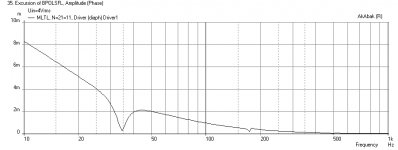
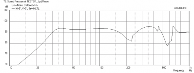
The design is 7.5 in wide x 6 in deep x 30 in long TL, with a 1.0 in x 3.75 in wide x 8.0 in long vent at the bottom. Put 4 in of the vent inside the box,4 in outside the box, stand it up on 8 in legs so that vent face is 4 in from floor (very important). Mount driver at 12 in from the top of cabinet. Stuff the first 1/2 to top 2/3rds of cabinet between 0.5 lbs to 0.75 lbs/cubic ft. The stuffing will smooth out the peaks and dips due to cabinet length resonances.
Also, if you intend for the Silver Flutes to serve above 1 kHz, you should add a BSC circuit of 4 ohm + 1.5 mH inductor in parallel and put that in series with positive terminal to driver.
Attached are the simulation results including BSC circuit showing frequency response and also the driver displacement plot. This is for 8 watts of input power. Driver cone excursion seems to be well controlled.
I think that this may turn out to be a very nice design once stuffing is in place.
X
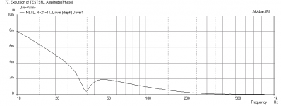
OK, I took another crack at it not to be beat by a low Qts driver. My problem was I had the down firing vent set too high above the floor. This low Qts driver makes for a very small slender cabinet that is not too long either so you will not get the 48 in height.
The design is 7.5 in wide x 6 in deep x 30 in long TL, with a 1.0 in x 3.75 in wide x 8.0 in long vent at the bottom. Put 4 in of the vent inside the box,4 in outside the box, stand it up on 8 in legs so that vent face is 4 in from floor (very important). Mount driver at 12 in from the top of cabinet. Stuff the first 1/2 to top 2/3rds of cabinet between 0.5 lbs to 0.75 lbs/cubic ft. The stuffing will smooth out the peaks and dips due to cabinet length resonances.
Also, if you intend for the Silver Flutes to serve above 1 kHz, you should add a BSC circuit of 4 ohm + 1.5 mH inductor in parallel and put that in series with positive terminal to driver.
Attached are the simulation results including BSC circuit showing frequency response and also the driver displacement plot. This is for 8 watts of input power. Driver cone excursion seems to be well controlled.
I think that this may turn out to be a very nice design once stuffing is in place.
X
Attachments
![Silver Flute W17RC38-08 MLTL - dual [measured].gif](/community/data/attachments/316/316117-857b6135130f3d0129c1c2a3ba32af66.jpg)
![Silver Flute W17RC38-08 MLTL - dual response [measured].gif](/community/data/attachments/316/316123-9515569731dad32d1c0061f058db5df0.jpg)
- Status
- This old topic is closed. If you want to reopen this topic, contact a moderator using the "Report Post" button.
- Home
- Loudspeakers
- Full Range
- Tangband W3-881 MLTL build