Hi permo,
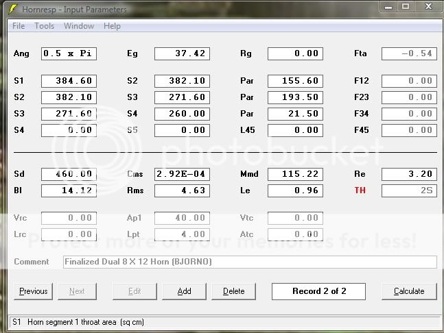
There are some minor differences between your and bjorno's T/S numbers, but I don't think that matters. The difference is in the areas. From the drawing, e.g.: the "Duct height @ S1=6.912"...". The front view shows the internal width to be 8.625", when you multiply these two numbers you get a cross-sectional area S1=6.912 x 8.625, or S1=59.616in^2 [384.6cm^2].
I rechecked the numbers in my Hornresp input screen from Post #58, and I think they reflect the drawing.
Regards,
Hi permo,
There are some minor differences between your and bjorno's T/S numbers, but I don't think that matters. The difference is in the areas. From the drawing, e.g.: the "Duct height @ S1=6.912"...". The front view shows the internal width to be 8.625", when you multiply these two numbers you get a cross-sectional area S1=6.912 x 8.625, or S1=59.616in^2 [384.6cm^2].
I rechecked the numbers in my Hornresp input screen from Post #58, and I think they reflect the drawing.
Regards,
wow, I didn't realize the S numbers in hornresp represent the entire area of the segment. Thanks again!! Wow does that make a difference! Strong down do 20hz....awesome. Really awesome.
Last edited:
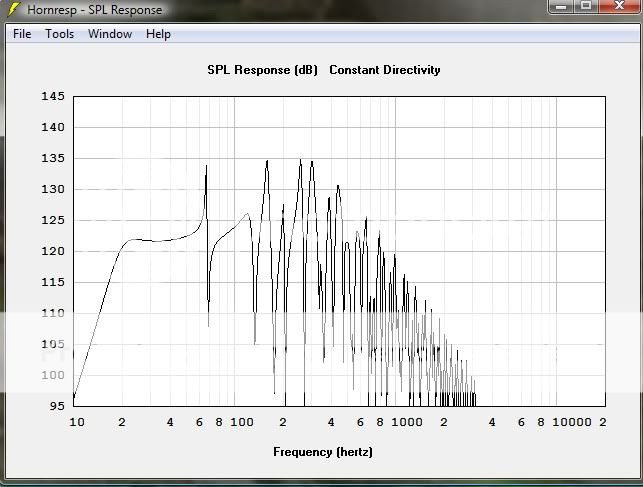
Well, I plan on corner loading this subwoofer...the hornresp SPL response window claims 120db at 20 hz is a possibility. Holy crap!
Are you thinking that dampening/stuffing material is only needed in the S1 area?
Also, the mounting depth is 5 3/4 inches. I don't think I will even have to invert one since duct height at s2 (behind drivers) is 6.66 inches. Unless there is some reason that they driver should be inverted?
Are you thinking that dampening/stuffing material is only needed in the S1 area?
Also, the mounting depth is 5 3/4 inches. I don't think I will even have to invert one since duct height at s2 (behind drivers) is 6.66 inches. Unless there is some reason that they driver should be inverted?
Last edited:
Hi permo,
Post #63:
"...that dampening/stuffing material is only needed in the S1 area?"
Maybe you'll try stuffing only the vertical going down from S1 first, and then try to use the stuffing as bjorno indicated in Post #13. Polyfill is fine. Maybe bjorno can advise you as to the density and the density distribution.
"...some reason that they driver should be inverted?"
The drivers should fit fine without inverting one of them, I just indicated that as an option. The main reason you'll find that type of Push-Pull arrangement is for distortion cancellation. (Obviously, you don't want to invert the driver polarity on one driver if you are not inverting it mechanically.)
Cut any wood yet?")
Regards,
Post #63:
"...that dampening/stuffing material is only needed in the S1 area?"
Maybe you'll try stuffing only the vertical going down from S1 first, and then try to use the stuffing as bjorno indicated in Post #13. Polyfill is fine. Maybe bjorno can advise you as to the density and the density distribution.
"...some reason that they driver should be inverted?"
The drivers should fit fine without inverting one of them, I just indicated that as an option. The main reason you'll find that type of Push-Pull arrangement is for distortion cancellation. (Obviously, you don't want to invert the driver polarity on one driver if you are not inverting it mechanically.)
Cut any wood yet?
Regards,
Hi permo,
Post #63:
"...that dampening/stuffing material is only needed in the S1 area?"
Maybe you'll try stuffing only the vertical going down from S1 first, and then try to use the stuffing as bjorno indicated in Post #13. Polyfill is fine. Maybe bjorno can advise you as to the density and the density distribution.
"...some reason that they driver should be inverted?"
The drivers should fit fine without inverting one of them, I just indicated that as an option. The main reason you'll find that type of Push-Pull arrangement is for distortion cancellation. (Obviously, you don't want to invert the driver polarity on one driver if you are not inverting it mechanically.)
Cut any wood yet?
Regards,
Oh I will invert them for sure then.
Bjorno even shows in his diagram where to put the polyfill.
I have bought the wood, but I am trying to find somebody to borrow a table saw from at this point. I don't want to use a circular skil saw for this. I want it exact. I have two sheets of 3/4 inch BCX plywood for the first run...heck if it looks and sounds good I will just keep it that way.
You guys are great!
Last edited:
..Bjorno even shows in his diagram where to put the polyfill.
Hi Permo,all
Here is a hint(s) on the required Weight/Density of damping material:
Thank you Oliver for your contribution so far. My speed when answering threads like this is of a
 , almost always too late or too short when writing...
 Permo, What's visible for non members here is your input screens in post# 57/60 that may for non members might be very confusing: Why not post a corrected one that should reflect your build intention's?.
b
Attachments
Last edited:
Here is a hint(s) on the required Weight/Density of damping material:
b
Thank a million!! Wow for information
Here is the hornresp input screen for the latest and greatest. -3 of 18hz!! AWESOME
Here is the SPL response for a corner location @ 200 watts. WOW
I am very excited to start putting this thing together, slowly but surely. THe removable panels will be the engineering challenge. I am putting more time into design and preparation, I want to get this one right!
Last edited:
Thank a million!! Wow for information
Here is the hornresp input screen for the latest and greatest. -3 of 18hz!! AWESOME
Here is the SPL response for a corner location @ 200 watts. WOW
I am very excited to start putting this thing together, slowly but surely. THe removable panels will be the engineering challenge. I am putting more time into design and preparation, I want to get this one right!
Thank you Permo.. I guess you should take 200W Rms as a maximal headroom limit and stay at SpL's that doesn't wreck you house or your ears...or shred your driver paper cones...
b
Thank you Permo.. I guess you should take 200W Rms as a maximal headroom limit and stay at SpL's that doesn't wreck you house or your ears...or shred your driver paper cones...
b
I suppose so, I am just really looking forward to building this thing. I was thinking of a few different ways to build access hatches. The problem is that I don't want to create airflow disturbances so the tolerances have to be right on! I will be taking my time with this project!
Just an update here guys. Here is my cut sheet, in inches.
Two - 21 9/16" X 51 11/16" Sides (MDF, particle Board)
One - 8 5/8" X 51 11/16" Rear (MDF, particle Board)
One - 8 5/8" X 4 11/16" Bottom Front (below slot) (MDF, particle Board)
One - 8 5/8" X 42 11/32" Top Front (Above Slot)(MDF, particle Board)
Two - 8 5/8" X 20 1/8" Top and Bottom (MDF, particle Board)
One - 8 5/8" X 43 5/16" Vertical Divider(MDF, particle Board)
One - 8 5/8" X 44 5/16" Slanted Board ( for drivers)(MDF, particle Board)
One 8 5/8" X 14" for inverted driver spacer (plywood)
My math is as close as I could get to matching the dimensions in the PDF's. They aren't off by much..hundreths of an inch if anything. Somebody can double check my work, but I think they are very accurate. With these drivers on sale at PE I figured this cut list, in addition with all the REDICULOUS documentation and modeling from TB46 and BJORNO could get some other DIY folks on the fast track to some serious bass.
Once I have this all assembled and in place I am going to add some braces and consider my options for creating removable hatches. I have a fairly good idea that I think will be better served by pictures when the time comes.
Last edited:
Hi permo,
Those dimensions look basically good. The slanted (driver) board measures 44.454"(~44 7/16" = 44.375") in the drawing. For the top and bottom boards I would suggest 20 3/32".
You may want to keep in mind the possibility of a round port, which may be easier to build.
Also, if you don't invert the upper driver you only need a front access panel.
Pictures sounds great.
Regards,
Hi permo,
Those dimensions look basically good. The slanted (driver) board measures 44.454"(~44 7/16" = 44.375") in the drawing. For the top and bottom boards I would suggest 20 3/32".
You may want to keep in mind the possibility of a round port, which may be easier to build.
Also, if you don't invert the upper driver you only need a front access panel.
Pictures sounds great.
Regards,
If I don't invert the driver, do you think a double thick baffle area (maybe about 30 inches worth, would be a good idea up the baffle board? Maybe router the top edge so be smooth? I should just leave well enough alone probably.
updated cut sheet.
two 21 9/16 X 51 11/16 Sides (MDF, particle Board)
One 8 5/8 X 51 11/16 Rear (MDF, particle Board)
One 8 5/8 X 4 11/16 Bottom Front (below slot) (MDF, particle Board)
One 8 5/8 X 42 11/32 Top Front (Above Slot)(MDF, particle Board)
two 8 5/8 X 20 3/32 Top and Bottom (MDF, particle Board)
one 8 5/8 X 43 5/16 Vertical Divider(MDF, particle Board)
One 8 5/8 X 44 7/16 Slanted Board ( for drivers)(MDF, particle Board)
One 8 5/8 X 14 for driver spacer (plywood)
Hi permo,
I think a single baffle will be fine (considering the width of the board), additional braces will also stiffen this board. Rounding the upper edge sounds like a good idea, and rounding the free edge on the vertical divider as well.
Take another look at how DrDyna (http://www.diyaudio.com/forums/subwoofers/188283-fiddling-hornresp-peerless-831759-a-2.html Post #20) solved his access lid. you could do the same thing, using a circular port would make it one panel about 26-27" long x 10 5/8" wide, it would mount against the sides and the bottom, and against the fixed portion of the front panel (rabbeted). That would be about the easiest solution. Also, you could insert a metal cross-brace connected to the fixed portion of the front panel and the sides, something 1/8" thick would not affect the performance.
Just a lot of ways to do this.
Regards,
Hi permo,
I think a single baffle will be fine (considering the width of the board), additional braces will also stiffen this board. Rounding the upper edge sounds like a good idea, and rounding the free edge on the vertical divider as well.
Take another look at how DrDyna (http://www.diyaudio.com/forums/subwoofers/188283-fiddling-hornresp-peerless-831759-a-2.html Post #20) solved his access lid. you could do the same thing, using a circular port would make it one panel about 26-27" long x 10 5/8" wide, it would mount against the sides and the bottom, and against the fixed portion of the front panel (rabbeted). That would be about the easiest solution. Also, you could insert a metal cross-brace connected to the fixed portion of the front panel and the sides, something 1/8" thick would not affect the performance.
Just a lot of ways to do this.
Regards,
The circular port would make this easier for sure...just remove the entire front pannel for access.
I just love the look of the slot port for some reason.
Cut sheet update, designed with front removable panel (entire panel) and circle port.
The front and rear now sit on the sides. I will weather strip the front so it is removable as a whole....or something along those lines. Once i start putting it together I may change plans, but I will keep updating this thread and add pictures of the process.
two 20 1/16 X 51 11/16 Sides (MDF, particle Board)
One 8 5/8 X 51 11/16 Rear (MDF, particle Board)
two 10 1/8" X 51 11/16 Front (removable) and Rear
Round Port 7 inches from Bottom 7 1/8 inch in diameter
two 8 5/8 X 20 3/32 Top and Bottom (MDF, particle Board)
one 8 5/8 X 43 5/16 Vertical Divider(MDF, particle Board)
One 8 5/8 X 44 7/16 Slanted Board ( for drivers)(MDF, particle Board)
One 8 5/8 X 14 for driver spacer (plywood)
I hope I didn't make any errors, but I think it looks good. A good plan is coming together!!
Thoughts on materials to be used? It would be best if it looked good...Oak or Birch plywood or is pine ok? I want to sand and stain all external pannels. May even add some trim.
Last edited:
Hi permo,
If you make the sides 20 1/6" wide than the front and back panels have to be mounted from the front and the back, they have to be 10 1/6" wide (10.065). You won't need an additional "One 8 5/8 X 51 11/16 Rear (MDF, particle Board)". I would make both, the front and the rear removable. You also don't need the driver spacer, if you mount both from the front.
Make certain that you get the position of the slanted driver board, and the vertical divider correct; the dimensions in the drawing are from the outside edge of the box, for reduced size side boards you'll need to reduce the dimensions from the front and the back by .720" (e.g.: 6.394 becomes 5.674).
Regards,
Here is my plan, with removable top front panel (Top and Bottom) and original slot opening design. I am hoping that making the top and bottome ledge of the slot opening an extra .72 inches in thickness towards the outside doesn't cause any issues. I think this should be a great solution. It will make for a slightly heavier enclosure, but also more robust... it will limit front panel to angled baffle bracing, but I can still brace the crap out of the rest! I put my solution for removable front, in blue.
two 21 9/16” X 51 11/16” Sides (MDF, particle Board)
One 8 5/8 X 51 11/16 Rear (MDF, particle Board)
One 8 5/8” X 4 11/16” Bottom Front (below slot) (MDF, particle Board) (do not seal into enclosure)
One 10 1/8" X 4 11/16" Cap for bottom front below slot to match board below (weather strip seal)
One 8 5/8” X 42 11/32” Top Front (Above Slot)(MDF, particle Board) Do not seal this one into enclosure
One 10 1/8" X 42 11/32" Attach to board above and seal using weather stripping. This will facilitate removable top front panel. (Handles?)
two 8 5/8” X 20 3/32” Top and Bottom (MDF)
one 8 5/8” X 43 5/16” Vertical Divider(MDF)
One 8 5/8” X 44 7/16” Slanted Board ( for drivers)(MDF)
Last edited:
Hi permo,
Post #78: "I am hoping that making the top and bottome ledge of the slot opening an extra .72 inches in thickness towards the outside doesn't cause any issues."
You are correct, that will not change the response of the enclosure much; you can test for the effect of changes in Hornresp, in this case just add 1.8cm to L34. You'll also need access from the rear to work with the stuffing in the L12 section.
Hope you're making good progress.
Regards,
Hi permo,
Post #78: "I am hoping that making the top and bottome ledge of the slot opening an extra .72 inches in thickness towards the outside doesn't cause any issues."
You are correct, that will not change the response of the enclosure much; you can test for the effect of changes in Hornresp, in this case just add 1.8cm to L34. You'll also need access from the rear to work with the stuffing in the L12 section.
Hope you're making good progress.
Regards,
Good call, virtually no change, if anything a very mild low frequency (20hz and down) improvement.
I will make the same removable panel for the rear.
Turns out this thing is going to weigh ALOT.
I have not cut any wood yet, but I owe it to you guys to post pics along every step of the way as I start, and I promise to do so.
- Status
- This old topic is closed. If you want to reopen this topic, contact a moderator using the "Report Post" button.
- Home
- Loudspeakers
- Subwoofers
- Tang Band Tang Band W8Q-1071F 8 X 12 box reccomendation