So here is the updated drawing with today's mods.
I had a chance to crank it a bit. everything seems more balanced now. It took a little of the shout out from voices which is always nice.
The sound-stage sounds physically lower as well, before voices sounded "higher" up , as if you were staring up at a stage.
Now it sounds "in front" of me. Now I can rest me neck. Feels good.
Attachments
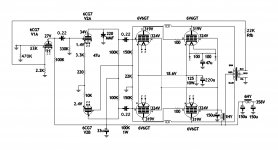
Ok so I went and added 1K gridstoppers to the 6V6 tubes today.
I also swapped the plate resistors for the second stage 6CG7 and paraphase inverter back to 470K.
I put the inverter back closer to stock removing the 150K and putting in 220K.
Not really any difference in sound despite the changes.
The changes the other day had the most effect on sound in a good way.
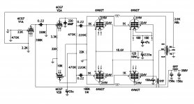
Here is the schematic as it is today.
I also swapped the plate resistors for the second stage 6CG7 and paraphase inverter back to 470K.
I put the inverter back closer to stock removing the 150K and putting in 220K.
Not really any difference in sound despite the changes.
The changes the other day had the most effect on sound in a good way.
Here is the schematic as it is today.
Attachments
You still having a problem with the gain of the whole system mismatching your volume control? i have a idea if so.
I know you intended to keep it in triode mode, but the circuit makes this modification so simple. Add a resistor before/after that 1 HY inductor to knock down the voltage on your screen grids. beam tetrode/pentode gain raises/falls with screen grid voltage so if you knock for instance 20v you will have noticeably less gain. if you really wanted to take a wild experiment you could bring it all the way down to 200~250v
edit: my on hand datasheet for 6v6gta says 225v screen grid for 315v anode
Last edited:
It's pretty much under control now, having said that, I might try that.
Unbypassing the front end stage cathodes and adding griddstoppers did the trick.
I never did get around to switching in triode mode, but still intend to.
I really appreciate your response, I'm always looking for something to tinker with.
Unbypassing the front end stage cathodes and adding griddstoppers did the trick.
I never did get around to switching in triode mode, but still intend to.
I really appreciate your response, I'm always looking for something to tinker with.
It should be pretty straight forward, kinda looks like a pi-filter? -using the 1HY as the "L"?
maybe im not seeing your circuit right, but by the looks of it. your screen grids all combine and connect to that capacitor and then through the inductor to the b+ right?
if so put in a 20~25k ohm resistor or so in-line before or after that inductor. that should drop it by a fair share. my 807 screen grid at 420v anode and 315v screen grid consumes about 1.8 mA so around 1 mA for your scenerio i imagine?
Last edited:
taking another look at my datasheet, it says 2.2 mA idle current so 10k ohm is probably more like it. They are pretty safe to experiment with going up/down with.OK got it. I will hopefully get a little time tomorrow afternoon to try it.
Thanks again.
here, take a look.
http://ryujiwarui.com/data/6v6gta-rca.pdf
i find RCA datasheets to be closer to true to life in my experimenting, of course your milage may vary. also keep in mind that the RCA datasheet i linked is referring to class A operation. Screen grids can be tricky, experimenting gets you what you are seeking. Cant really complain. its just a single resistor
havent made the modification to it but i prototyped it and will do the full conversion to new architecture next week, but this is my new design
http://ryujiwarui.com/upload/Pure_Pentode-Rev4B.png
name is slightly incorrect as its a beam tetrode and not quite pure pentode mode
take a look at this folder if your browsing around")
Index of /tube/current
5 channel single ended amplifier with subwoofer preamp
edit:
actually, more likely that ill be distracted with building my aikido 6SN7GTB based headphone amp
no comments in this thread on stuff on my site, pm only threadjack not intended.
http://ryujiwarui.com/upload/Pure_Pentode-Rev4B.png
name is slightly incorrect as its a beam tetrode and not quite pure pentode mode
take a look at this folder if your browsing around
Index of /tube/current
5 channel single ended amplifier with subwoofer preamp
edit:
actually, more likely that ill be distracted with building my aikido 6SN7GTB based headphone amp
no comments in this thread on stuff on my site, pm only threadjack not intended.
Last edited:
i mostly am following john broskie's design for the aikido octal headphone amplifier. ill make a thread once i get everything put together and start making modifications.
if you want to do similar go order one of his pcb's. i ordered one on glowing recommendation of my best friend
if you want to do similar go order one of his pcb's. i ordered one on glowing recommendation of my best friend
i have one on hand. im just missing misc parts and the tubes. it neatens up things a lot to have the traces instead of point to point.
ordered these for the coupling to my 200 ohm headphones. Just need to wait for all my power supply parts and coupling caps to arrive.
ASC High Capacitance Polypropylene Film 80uf / 330vac AC Filter Caps | eBay
http://www.tubecad.com/Product_PDFs/Octal_Stereo_Rev_C.pdf
oh hope you got high impedance headphones, 32 ohms requires electrolytics in the signal path due to such low output impedance >.> or matching transformers/different tube choice
Last edited:
No my cans are 32 ohms. Guess it gives me an reason to find some different ones.
Odd, I'm looking at some Grado's on eBay, I thought they were 300 ohm. Maybe I'm thinking of Sennheisers's
I'm reading over the GlassWare article now.
My little cMoy got me into this hobby a few years back. It would be nice to have a tubed can amp.
Odd, I'm looking at some Grado's on eBay, I thought they were 300 ohm. Maybe I'm thinking of Sennheisers's
I'm reading over the GlassWare article now.
My little cMoy got me into this hobby a few years back. It would be nice to have a tubed can amp.
- Status
- This old topic is closed. If you want to reopen this topic, contact a moderator using the "Report Post" button.
- Home
- Amplifiers
- Tubes / Valves
- Tame the beast.