Rob,
And the corollary that follows from that (IMHO), is that you should place the driver higher (maybe closer to where you were putting in originally), to eliminate the resonance at 240 Hz, and ignore what "damage" it may appear to do at the higher frequencies.
Ooops, I wrote higher, but meant lower (closer to port end), sorry!
Eric
Hi
Another problem with long ports is than the total volume of the pipe decreases. Meaning lower output from the opening.
Bjorn,
Do you think the drop in output with an increase port length is more than what the models predict?
No doubt, that effect is predicted by LA-TL and presumably also by the MLK model, but there is a range in which the effect seems negligible.
Do you have a "rule of thumb" for port length?
Eric
I have no idea what the "ideal" un-stuffed plot should look like
Rob,
I don't know either, but I do know what I think I want!
My target (unstuffed) is something like this, where:
(1) the driver is positioned to eliminate the 3/4 wave resonance.
(2) the system SPL is pretty flat beween the first peak and the 5/4 wave resonance (100 to 500 Hz in this example)
(3) the low frequency SPL peak is in the range of 3-5 dB above the plateau that follows.
I got the results below using your driver and cabinet design, but with the main line 60 cm long, the port 8 cm long, and the driver at about 29 cm from the closed end. I used the same cross sections as you for the main line and port (128 and 16 cm2)
I'm not saying it's optimal by any means, but just that this is what I try to get.
Eric
An externally hosted image should be here but it was not working when we last tested it.
Interesting stuff you all... I'm following the discussion.
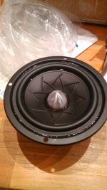
On another note, I just received the TB W4-1052SDF today and it looks awesome.
I placed it in my TABAQ test box, and all the ingredients seem to be there.
I will do a frequency sweep soon to see if I need BSC.
On another note, I just received the TB W4-1052SDF today and it looks awesome.
I placed it in my TABAQ test box, and all the ingredients seem to be there.
I will do a frequency sweep soon to see if I need BSC.
Attachments
<From the hammock under the shade of the tree>
Having used Leonard TL for a while...
I've come to think that having a gentle slope from the fundamental DOWN to the 3rd harmonic (first spikes) on the undamped plot is beneficial. Once damped, or stuffed, the port output reduces in line with stuffing density.
Secondly.... You can adjust the "slope" between the fundamental and the 3rd harmonic by adjusting the driver placement. If you eliminate the 3rd harmonic, you flatten the plot in between them. This may cause larger "effects" higher up in the plot.... For Tabaq and other single fullrange driver designs it may be more important to have a smoother response higher up.
J.
Thanks for the tip J! Hope you're getting to enjoy the hammock on the bank holiday too
")
I just had a play in the Leonard s/w and the angle of the "slope" between the left-most hump and the first discontinuity can be adjusted by changing the CSA of the main section. However this has the side-effiect of raising the frequency of the hump, presumably affecting bass roll-off.
Last edited:
Rob,
I don't know either, but I do know what I think I want!
My target (unstuffed) is something like this, where:
(1) the driver is positioned to eliminate the 3/4 wave resonance.
(2) the system SPL is pretty flat beween the first peak and the 5/4 wave resonance (100 to 500 Hz in this example)
(3) the low frequency SPL peak is in the range of 3-5 dB above the plateau that follows.
I got the results below using your driver and cabinet design, but with the main line 60 cm long, the port 8 cm long, and the driver at about 29 cm from the closed end. I used the same cross sections as you for the main line and port (128 and 16 cm2)
I'm not saying it's optimal by any means, but just that this is what I try to get.
Eric
An externally hosted image should be here but it was not working when we last tested it.
Thanks for all the info Eric!
I can reproduce your idea of putting the driver almost mid-way to eliminate that harmonic. I have no idea if this is a good thing or not, however!
My question about the minus-infinity / plus-infinity thing was about the discontinuities either end of the 'saddles' in the graph where the black (system SPL) line is going along horizontally, then starts to curve down (or up) exponentially and then shoots off to infinity. Then slightly to the right it comes back in from the opposite polarity.
Some saddles are n shaped where the discontinuity of the line comes in from minus-infinity, goes horizontal, then later curves down and shoots off to minus-infinity.
Other saddles are u shaped where the discontinuity of the line comes in from plus-infinity, goes horizontal then later curves up and shoots off to plus-infinity. Occasionally you get a saddle which is neither n nor u shaped, e.g. where the discontinuity of the line comes in from minus-infinity, goes horizontal then shoots off to plus-infinity. I guess these are kind of s-shaped saddles. I was wondering about the significance of the saddles being n, u or s-shaped, and whether they should be neatly alternating, or if one type (s-shaped) was particularly undesirable.
Thanks for all the info Eric!
I can reproduce your idea of putting the driver almost mid-way to eliminate that harmonic. I have no idea if this is a good thing or not, however!
You're welcome. I for one do think it's a good idea to position the driver that way, but I am aware (and you should be too) that many well respected designers do not prefer that position.
The arguments against it (as I understand them) include:
(1) It may put the driver below "ear" height. Since drivers are very directional, it's ideal to have them at ear level. To that argument I suggest putting the speaker on a stand, or building the stand into the cabinet, but some may not prefer to do that.
(2) Overall output is reduced as the driver is moved farther from the closed end. This seems to be true, however, the LA-TL model shows this to be a very small effect in the examples I have tried, so I don't worry about it. Try it and decide for yourself if it's significant.
(3) With an MLTL, the peaks are pretty easily damped with light stuffing, so eliminating any peaks with driver positioning is just not that critical. I concede there is some truth to this too. Compared to a straight TL, the peaks in an MLTL are very subtle. But I'd I'd still rather improve what I can by using strategic driver positioning.
Regarding the n and u and s shaped saddles: I don't worry about them and never gave them much consideration. I'll be interested to see what others say about them. My thinking has always been that the best you can hope for (in the un-stuffed model) is that the plateaus between the saddles would be at close to a constant SPL, and assume that the stuffing would eliminate the spikes.
Also, as I mentioned before, as I look at higher and higher frequencies I tend to expect that the terminus contribution will become more negligible. Therefore, when looking at the high frequency portion of the unstuffed results, I focus more on driver SPL and less on system SPL. I could be misguided, however....
Eric
Hi Veleric, I will do some MJK sims to verify your idea.
I like your approach that you have a design goal. I sometimes sim "the best possible solution for a driver" but it often conflict with the acceptable size og the speaker.
PS: One of the benefits of TL and the stuffing is that cone movement below tuning is reduced. Meaning cleaner bass and reduced noise. Try to feed a BR with a sinus tome below tuning and you will see what I mean.
Bjørn
Bjørn,
Glad to see your reply. I was worried you'd say something like "oh no, ignore him, he's got it all wrong..."
And i'm interested to see what the MJK sims show. The LA-TL shows just what I described, so I think (and hope) the MJK sim will too.
The only caveat is that the driver position to eliminate a particular resonance is always just a tiny bit farther down the line than the exact theoretical ratio. For example, I just looked at a sim of a 150 cm long TL, and the driver position to eliminate the 3/4 wave resonance was at 52 cm from the closed end, instead of exactly 50 cm (L/3) that would be expected from simple theory.
I suspect that this is due to end-effects being incorporated into the model. That is, the model knows that a 150 cm pipe will actually behave as if it has a slightly longer effective length. So L/3 is still the correct position, it's just that "L" is the effective length rather than the measured length.
Likewise the next resonance is eliminated at a driver position of 31 cm instead of exactly 30 cm (L/5). All the "critical" positions will be close to L/3, L/5, L/7, etc, but not exact.
Eric
The only caveat is that the driver position to eliminate a particular resonance is always just a tiny bit farther down the line than the exact theoretical ratio. For example, I just looked at a sim of a 150 cm long TL, and the driver position to eliminate the 3/4 wave resonance was at 52 cm from the closed end, instead of exactly 50 cm (L/3) that would be expected from simple theory.
I suspect that this is due to end-effects being incorporated into the model. That is, the model knows that a 150 cm pipe will actually behave as if it has a slightly longer effective length. So L/3 is still the correct position, it's just that "L" is the effective length rather than the measured length.
Likewise the next resonance is eliminated at a driver position of 31 cm instead of exactly 30 cm (L/5). All the "critical" positions will be close to L/3, L/5, L/7, etc, but not exact.
Haha, I just realized that I was confusing this thread with one on the Quarterwave forum. So the comments above don't actually apply to robskillz design or this thread at all, sorry!
But I'm still interested to see how Bjorn's MJK sim comes out.
Eric
Hey Bjørn,
Yes the goal for me is to create the shortest TABAQ that sounds good, with bass that extends as low as possible. It would be great to get some input from you on whether your sims of these shorter TABAQ's look acceptable. The dimensions I used in my sims using the W3-315SC parameters were:
Main section length 57.58cm, CSA 128 cm^2
Vent length 12.46cm, CSA 16cm^2
Driver position 7.2cm or 14.5cm or 27.8cm
Last edited:
PS: One of the benefits of TL and the stuffing is that cone movement below tuning is reduced. Meaning cleaner bass and reduced noise. Try to feed a BR with a sinus tome below tuning and you will see what I mean.
I've hear of this in the past, but I don't see any evidence of it in the LA-TL model, as far as I can recall.
Does this effect show up in the MJK models? And if so, what does it look like? Lower cone displacements for a given power below tuning?
Thanks,
Eric
Hi Eric
Yes, it is shown in the cone displacement.
You can also see it in the impedance measurement. Unstuffed TL look very much like a BR with the two peaks around the tuning - where cone movement is at the lowest.
As you stuff the TL you will see that the lower peak, below tuning, will decrease.
Bjørn
Yes, it is shown in the cone displacement.
You can also see it in the impedance measurement. Unstuffed TL look very much like a BR with the two peaks around the tuning - where cone movement is at the lowest.
As you stuff the TL you will see that the lower peak, below tuning, will decrease.
Bjørn
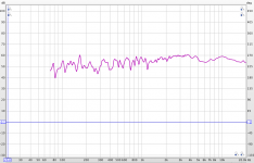
Here's what the W4-1052SDF looks like in the TABAQs.
This is taken at a lower spl because I am still breaking in the drivers. Also, TABAQ was away from the back wall, so, would not need a BSC if placed closer to the back wall.
Not too bad.
This is taken at a lower spl because I am still breaking in the drivers. Also, TABAQ was away from the back wall, so, would not need a BSC if placed closer to the back wall.
Not too bad.
Attachments
Last edited:
Yes, great to see Bjorn's sim's and commentary.
As Bjorn mentioned, I also would not worry much about the 60 Hz bump. That said, I also wanted to add, however, that if you wanted to reduce it, you could do so by reducing the cross sectional area of the line. Of course, to preserve the same tuning the line would have to get a little longer, and the driver position moved (a little) to achieve a similar elimination of the chosen overtones. Again, I'm not say you should (or should not) make such a modification, just pointing out (for academic sake) what could be done.
Bjorn, I am a bit curious about why you prefer the 14.5 cm position over the 27.8 cm position. In both cases the magnitude of the first nasty peak seems about the same, so I don't see any reason for preference on that basis. My thinking is that the higher frequency stuff is easier to damp out than the lower, so I'd rather clean up the lower frequency peak (about 320 Hz) using driver location than the higher frequency peak (about 600 Hz). Could you explain your reasoning?
Thanks,
Eric
Personally, I would hate having to deal with two peaks so close to the "telephone" frequencies around 1k.
Separating the peaks looks like a good idea to me.
Thanks!
I plan to put them as close to the wall as possible.
Those W4-1052SDF are very tight and punchy. Pleasantly surprised from this polypropylene cone.
Separating the peaks looks like a good idea to me.
Hi perceval
Nice, my 4" are at the wall - no BSC.
Regards
Bjørn
Thanks!
I plan to put them as close to the wall as possible.
Those W4-1052SDF are very tight and punchy. Pleasantly surprised from this polypropylene cone.
Hi Eric
It is true the higher peaks in the 27.8 position only require light stuffing, but you have to take care of the peak in the low end to avoid boomy bass - you must include room gain - which requires more stuffing to control.
Another thing: The 14,5 speaker will look nicer
PS: Reducing the cross section would not change the tuning frequency very much. Maybe a couple of Hz at the most. The output from the port will drop if you reduce the cross section, meaning less bass.
Hi
Bjørn
- Home
- Loudspeakers
- Full Range
- TABAQ TL for Tangband