Hi Dimitri,
actually I had two reasons to use single transistors.
a) I had them in my assortment.
b) Heat dissipation. IRFB4115 is as heavy as 4227 or 4229 and at 400kHz you will see the related heat in the driver section. The detailed loss sharing in the driver components (BJT, diode, resistor..) will depend on the specific solution.
In fact the detailed optimization of the gate drive has to be done on the real thing, not in simulation. Consequently I had chosen the BJTs for worst case.
You are right the level shifting driver is the IRS20957.
Hi L.C.
Benefits:
Less voltage ripple on the output.
As a consequence of less voltage ripple, it is easier to go for high loop gain.
Or if you choose to stay with the same voltage ripple at the output, you will have a faster output filter, which allows a faster loop compensation and improved step response.
Downsides:
Higher switching losses.
Increased issues with deadtime distortion and/or commutation distortion.
Some years ago, in a moment of curiosity, I tuned my older proto from 2008 to 1MHz. Chasing the IRFB4321 (older brother of 4115) with 1MHz was a devil's ride and amazingly even stressing the poor thing beyond its SOA did not cause defects.. But frankly speaking, that's not advisable for a proper design.
IMHO 1MHz with current real life MosFets can make sense up to 200W in half bridges or 400W in full bridges, but not in the 1-2kW range.
Where should be input diamond stage and current follower on this diagram? I may mix something up. Thx
In this diagram you do not need to put a diamond stage nor a folded cascode.
It is just my personal taste that I substituted the fast OP amp stage with the diamond and folded cascode.
For this I also splitted the feedback structure, because the discrete gain stage offers best virtual GND properties at the emitters of the folded cascode and at the same time the current feedback network at the diamond allows various gain adjustments while providing a high input impedance for the audio signal.
Hi Choco,
I see good signs, at this point I'd be curious to see the work of the feedback in thd vs. frequency measurement.
for smps, since it is unregulated, whose behavior has the amplifier in 40-100Hz range? (i mean,in relation to your PSRR in this range fr).
regards
I see good signs, at this point I'd be curious to see the work of the feedback in thd vs. frequency measurement.
for smps, since it is unregulated, whose behavior has the amplifier in 40-100Hz range? (i mean,in relation to your PSRR in this range fr).
regards
Last edited:
It looks like you have LT1363 on board. So are you reserving diamond and folded cascode for another project? ThxIt is just my personal taste that I substituted the fast OP amp stage with the diamond and folded cascode.
AP2:
The loop structure of the shown measurements is mostly PID (with some further higher order signal shapers, which have minor influence in loop regulation).
So far I did not make THD measurements other than 1kHz.
Measurements at higher frequencies would touch pretty soon the limitations of my measurement equipment, because I am using a simple sound card and a 5th order passive low pass in front, which avoids irritating the sound card by carrier residuals. At 20kHz this filter already impacts -3db.
THD measurements at low frequencies should be easy, which frequency do you want to see?
Dimitri:
The LT1363 on my board is part of the triangle section, which is formed by the traditional comparator with hysteresis & integrator loop system (and an added step for the step shift).
The comparator is build in discrete, but the integrator of the triangle is using a LT1363. I did not find anything bad with the LT1363 at this point, it simply acts like in the school book.
The amplifier section has the options for the diamond and J-Fet input as well, but no option for an integrated solution ( which of course could be an interesting comparison).
The shown measurements where done with the diamond option according posting #11.
More details on the question from AP2.
Very clear his point is valid, if you want to run from unregulated supplies.
Please also refer to my posting #7. The version 1 would not allow for good PSRR, because it has no option to go for an integrating portion in the loop gain.
My measurements are done with the circuit of posting #11.
Please note that the network R32 and C8 is the key for PI portions.
In fact this network is the perfect place to add signal shapers and optimize loop gain details. Of course my optimized real proto has a more complex R-C-network than just R32 and C8.
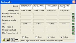
This morning I measured THD vs frequency at 60W into 2 Ohms, circuit identical to yesterday's measurements.
My equipment allows THD measurement in the frequency range 50Hz-7000kHz.
I divided this range into 4 steps, always increasing the frequency by factor 5.19 .
Very clear his point is valid, if you want to run from unregulated supplies.
Please also refer to my posting #7. The version 1 would not allow for good PSRR, because it has no option to go for an integrating portion in the loop gain.
My measurements are done with the circuit of posting #11.
Please note that the network R32 and C8 is the key for PI portions.
In fact this network is the perfect place to add signal shapers and optimize loop gain details. Of course my optimized real proto has a more complex R-C-network than just R32 and C8.
This morning I measured THD vs frequency at 60W into 2 Ohms, circuit identical to yesterday's measurements.
My equipment allows THD measurement in the frequency range 50Hz-7000kHz.
I divided this range into 4 steps, always increasing the frequency by factor 5.19 .
Attachments

Here the full picture of the THD.
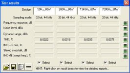
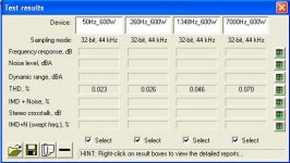
THD from 50Hz to 7kHz for 600mW, 6W, 60W and 600W.
THD from 50Hz to 7kHz for 600mW, 6W, 60W and 600W.
Attachments

Thank Choco..that very good value (if your software play right) 
Not know your real scheme in all, bat i'm sure you have find a good feedback phase/value, in good way of input stage.
last question...what is idle current on power stage? (input no signal).
I think you have low value,refer to dt on your signal.
Obvius, nice job.
Not know your real scheme in all, bat i'm sure you have find a good feedback phase/value, in good way of input stage.
last question...what is idle current on power stage? (input no signal).
I think you have low value,refer to dt on your signal.
Obvius, nice job.
The idle current consumption is 67mA.
With +/-62V rails (unloaded) this translates to 8.3W idling losses in the power stage. Which is 1.14% of the max output power (clipping at approx. 730W).
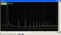
Of course measuring harmonics in the range of -90db... -100db is always like chasing ghosts. Nevertheless, I hope that the measurements are not completely wrong, up to now I do not have the impression that my equipment is tricking me completely. But I have no reference measurement with and AP or similar...
In the beginning the values were about one decade worse and it required a lot of fine tuning to get it right.
And still now it is not perfect. The level is really nice, but the spectrum offers room for improvement.
...the PCB allows to place an inductor with an Amidon torroid, let's see if this is better/worse/identical.
Attached the spectrum at 1kHz / 60W into 2R.
Amp unchanged as it is since yesterday with a gapped ferrite inductor.
With +/-62V rails (unloaded) this translates to 8.3W idling losses in the power stage. Which is 1.14% of the max output power (clipping at approx. 730W).
Of course measuring harmonics in the range of -90db... -100db is always like chasing ghosts. Nevertheless, I hope that the measurements are not completely wrong, up to now I do not have the impression that my equipment is tricking me completely. But I have no reference measurement with and AP or similar...
In the beginning the values were about one decade worse and it required a lot of fine tuning to get it right.
And still now it is not perfect. The level is really nice, but the spectrum offers room for improvement.
...the PCB allows to place an inductor with an Amidon torroid, let's see if this is better/worse/identical.
Attached the spectrum at 1kHz / 60W into 2R.
Amp unchanged as it is since yesterday with a gapped ferrite inductor.
Attachments
Hi,
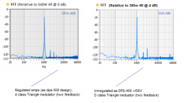
Hi, the measures are not bad, but just on fft, you have the classic defect of harmonics reversed, and repeated many harmonics. this does not adjust by changing the toroid unfortunately. responsible for this is the circuit that runs the dt and shape of the square wave in the driver circuit. of course, the feedback can help later.
sorry if placed two pic in your thread, maybe you can use as a reference. the second pic refers to similar your amplifier, the harmonics are resolved as you can see but it remained the second harmonic reversed. (this only characterize the sound, maybe it's not bad, sound similar at tube, of course fast.
the first pic is the best I got. by value and projection of the harmonics.
your low thd vs. frequency, is a great achievement (not easy), maybe you can get even better on the fft. this is all about how to play music on your amp.
P.S. for precision on measure...i see it's not bad, noise is flat on right ch. is better you ceck spectrum on generator also.
regards
Attachments
Last edited:
Your opinion is fitting to earlier results.
Earlier I had high k5 and k7, which I was able to bring down by 15db with adjustments in the gate drive.
So I will have a look to this direction again, thanks for remotivating me to optimize there.
I was already a little bit annoyed by the earlier gate drive adjustments...
P.S.
Your FFT is looking great !

Thanks Baldin and ionutzxpo for your friendly words.
I agree. The results are pretty good, but I have the silly and frustrating habit to look at the things which could be even better, like the spectrum.
So your comments make me feel better.
AP2:
Just checked the inductor. The Amidon seems to be marginal better at some harmonics, but not a big deal.
All my fast&blind trials on the gate drive did not bring much of an improvement nor a clear direction...
...have to look into the spectrum topic more systematical...
After many tests, observing the various behaviors, I use only Amidon, wired solid. but as you say, this has little influence with harmonics. surely you know well, which is not easy with triangular wave modulator, get good performances (such as class AB I mean). But you've already got a great result in the direction thd vs. freq.
I can advise you to reduce the dead-time, and see how they change the projections of the harmonics, this is a sign that you can work in this direction.
last test, are our ears about the "definition" of cimbals etc. .. hehe!
thanks for appreciating my fft on the new amp. This allowed comparison with large class AB in all. maybe is the best in this moment..
I showed just to say that you can.
Last edited:
Optimizing the spectrum is going to be a tough topic:
Of course the switching stage can be a key for this, but I am not convinced
anymore if it allows mayor improvement.
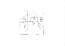
Attached the gate drive circuit, in order to simplify the discussion of the findings.
The starting point was R1 = 3R9 and D1 a MBR1100.
Cs 500pF and Rs 12R are optional and did show not have influence on the harmonics. It's more a cosmetic thing -at least with the said values.
Dead time of the IRS20957 was set to 25ns
1. Following AP2's proposal I reduced the dead time to 15ns.
==> K3 went up 10dB. Idle current consumption showed a moderate increase from 67mA to 83mA.
2. Hm, how about the opposite direction? Dead time of IRS20957 increased to 35ns.
==> K3 jumped 18dB upwards. An additional 9th grew 8db out of the noise floor.
3. Faster turn ON? R1 reduced to 1R95.
==> K3 went up by 10dB and a 9th and 10th grew out of the noise floor.
4. Slower turn ON? R1 increased to 6R8.
==> tons of k3 and K5
5. Slower turn OFF? An additional 1R2 in series with D1.
==> K3 went 10dB upwards. An additional 9th grew 10db out of the noise floor.
6. Speeding up the gate sloping before it would reach the plateau voltage area? A C1 with 2n2 was tried.
==> Almost identical effect like No.5.
Hm, let's still stay in the power stage area, but not gate drive.
Could it be the charging peak of the bootstrap supply?
7. Softening the charging peak of the bootstrap with a 3R3 in series to the bootstrap diode.
==> Slight increase of K3, most likely, because the resistor causes a voltage drop and the floating gate drive supply is slightly lower....
8. Softening the charging peak with and inductor of 2200nH.
==> Result like without anything...
Hm, I am already wondering if I should try my old di/dt limiter (i.e 15 nH with parallel 3R dampening resistor in the source leg), or Eva's ferrite bead in the gate? Unfortunately both not intended to reduce distortion, but to calm down HF resonances and would theoretically increase distortion....
Other open areas:
- Imperfections of the comparator?
- Further optimization of the signal shaping network?
- Imperfection of discrete gain stage?
- Imperfection of step shifted triangle (but looks perfect...)?
- Issue of the measurement equipment (but first check is Ok...)?
It is already a Toblerone, but I would love to cook it even more delicious.
Of course the switching stage can be a key for this, but I am not convinced
anymore if it allows mayor improvement.
Attached the gate drive circuit, in order to simplify the discussion of the findings.
The starting point was R1 = 3R9 and D1 a MBR1100.
Cs 500pF and Rs 12R are optional and did show not have influence on the harmonics. It's more a cosmetic thing -at least with the said values.
Dead time of the IRS20957 was set to 25ns
1. Following AP2's proposal I reduced the dead time to 15ns.
==> K3 went up 10dB. Idle current consumption showed a moderate increase from 67mA to 83mA.
2. Hm, how about the opposite direction? Dead time of IRS20957 increased to 35ns.
==> K3 jumped 18dB upwards. An additional 9th grew 8db out of the noise floor.
3. Faster turn ON? R1 reduced to 1R95.
==> K3 went up by 10dB and a 9th and 10th grew out of the noise floor.
4. Slower turn ON? R1 increased to 6R8.
==> tons of k3 and K5
5. Slower turn OFF? An additional 1R2 in series with D1.
==> K3 went 10dB upwards. An additional 9th grew 10db out of the noise floor.
6. Speeding up the gate sloping before it would reach the plateau voltage area? A C1 with 2n2 was tried.
==> Almost identical effect like No.5.
Hm, let's still stay in the power stage area, but not gate drive.
Could it be the charging peak of the bootstrap supply?
7. Softening the charging peak of the bootstrap with a 3R3 in series to the bootstrap diode.
==> Slight increase of K3, most likely, because the resistor causes a voltage drop and the floating gate drive supply is slightly lower....
8. Softening the charging peak with and inductor of 2200nH.
==> Result like without anything...
Hm, I am already wondering if I should try my old di/dt limiter (i.e 15 nH with parallel 3R dampening resistor in the source leg), or Eva's ferrite bead in the gate? Unfortunately both not intended to reduce distortion, but to calm down HF resonances and would theoretically increase distortion....
Other open areas:
- Imperfections of the comparator?
- Further optimization of the signal shaping network?
- Imperfection of discrete gain stage?
- Imperfection of step shifted triangle (but looks perfect...)?
- Issue of the measurement equipment (but first check is Ok...)?
It is already a Toblerone, but I would love to cook it even more delicious.
Attachments
Hello Choco, at this point, I also believe that the driver runs well. I know right now you're using IRS20957, this greatly reduces the points where you could fix something. from experience, I can assure you right in the input circuits, voltage split and buffer, are critical and can not be thought of only in logical criteria. Unfortunately, the engineers develop the chip, only with this criterion. you have already obtained an important result, certainly higher linearity than other amp chip. a low thd vs. frequency is not easy, because it depends on the structure of the feedback also.
you may stop here and your problems disappear ... hehe.
You can work on the triangular or comparator, in my opinion, you get an improvement of 2-3 dB on the projection of the harmonics. Perhaps many people think that a square wave is simple, does not think a distortion because it is already square.
this is wrong. actually contains a lot of information, just that they have changed in appearance. This is possibly a speech too complicated. justo for your curiosity, I use a triangular linear but I had to find out how to smooth edges (just for example), after that, I have developed all stages from the comparator to the mosfet gate. just i want decide how sound my amplifier.
Regards
Last edited:
In the mean time I started to listen to it. Most likely the best thing I ever did with this amp. ....still listening while writing these lines
Even being one channel only, it spreads pleasant vitality through the room.
Without blind test I have the impression that it offers slightly more
authority and control in deep bass compared to the rookie amps that I am listening since 5 years, while pleasing the ears with surprising human voices.
Nice new toy !!
I went on experimenting. Almost any change makes things less fortunate.
The set up seems to be already mostly in the optimum.
Another close-to-the-optimum-adjustment allows to bring down K3 further and get rid of the K9, but at the same time suffer a little bit on the K7. Overall still a similar wide spectrum, but all in the -100db area or less.
I also experimented with some ns additional delay, they systematically made things worse. Which is an important observation, from horse sense one could guess that some ns delay don't make difference compared to the group delay of the output filter.
The design has a propagation delay from comparator output to half bridge output of 140ns. From comparator input to half bridge output around 200ns.
And the group delay of the output filter.. - feel free to calculate/simulate on your own
... but adding just a few tens of ns already doubled the THD, unfortunately I cannot easily substract some tens of ns and see what would happen.
Overall I am glad that the amp really turns out to be well balanced over all disciplines.
- Fast and blameless step response, with rise times in the range around 4.5us
- Very forgiving on load impedance
- Almost free of carrier aliasing
- Blameless clipping recovery
- Low distortion over wide frequency range and over a wide power range, but with wide spectrum in the -100db range
- No annoying noise
- PSRR suitable for unregulated supplies
P.S: Still no indication of massive errors in the measurement equipment.
P.P.S: K11 is a known artefact of my measurement equipment.
P.P.P.S: The discrete gain stage has a very calm nature in the region K5, K7, K9.
P.P.P.P.S: The triangle allows similar possibilities for adjustments like the shaping network of the gain stage.
- Status
- This old topic is closed. If you want to reopen this topic, contact a moderator using the "Report Post" button.
- Home
- Amplifiers
- Class D
- System_D_MD, Class D is like chocolate