That was more or less my conclusion as well. Just to make things clear: we're talking 0 to 0.10 ms, not 10 ms! This would actually mean I don't have to delay any driver... But still the response looks odd, right, with that deep notch in the beginning?All the steps for >=0 ms delay show what seems to be the sharp rise of the CD interrupting the slow rise of the woofer to a greater degree with increasing delay. Up until 0, it seems nothing happens until the CD starts up. So you want to delay the CD a little more or the woofer a little less until they both start up at the same time.
Based on that, I suspect the optimum delay is somewhere between 0 and -10 ms.
Try to look at the individual driver responses that will help you to see which parts of the step belong to each driver.
Overlay them and use REW to delay the tweeter until the start of the woofer rise corresponds to the start of the tweeter impulse then check them combined. Jack has posted screenshots on his thread, look at those if the above doesn't make sense.
If you invert the polarity of the CD the peak will go down first which doesn't make sense to me if you are attempting to make the step look good which implies very good time alignment and positive phase.
Most multiway speakers have a terrible looking step but still sound good. It takes a bit of DSP work or careful positioning in the horn to get close acoustically.
Getting smooth phase through your crossover region would be a priority for me.
Try to look at the individual driver responses that will help you to see which parts of the step belong to each driver.
Overlay them and use REW to delay the tweeter until the start of the woofer rise corresponds to the start of the tweeter impulse then check them combined. Jack has posted screenshots on his thread, look at those if the above doesn't make sense.
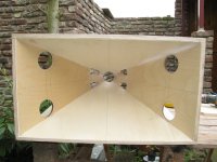
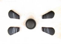
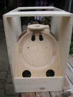
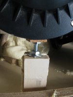
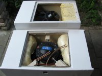
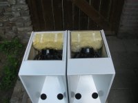
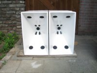
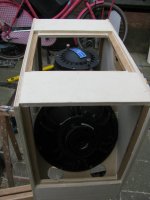
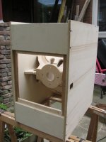
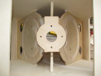
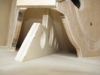
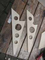
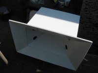
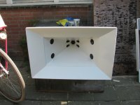
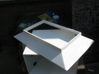
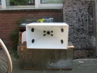
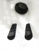
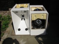
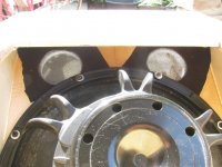
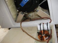
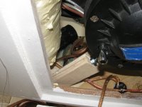
I have been working on a second prototype. It has smaller horn entry ports, so the center is a little closer to the throat and the bass reflex ports are located differently because I suspected the internal structure of the 1st proto type to form a longer bass reflex tunnel than intended. Here are some photos:
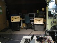
Yesterday I got a chance to take everything outside and take some measurements without the room influence, although I live in a city and it is not exactly quiet with traffic background noise... But still better than inside the room.
Measurement setup: speaker on household stairs, about 1.8 m from the ground and pointed upwards; measurements mic at 1.6 m above the mouth exit (more extension and my mic stand would fall over).
Now for the results...
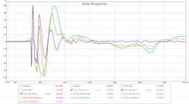
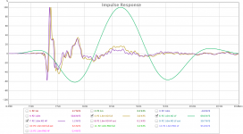
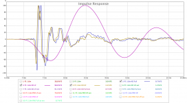
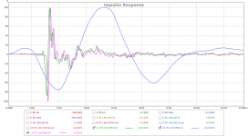
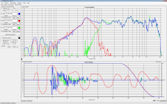
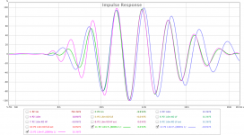
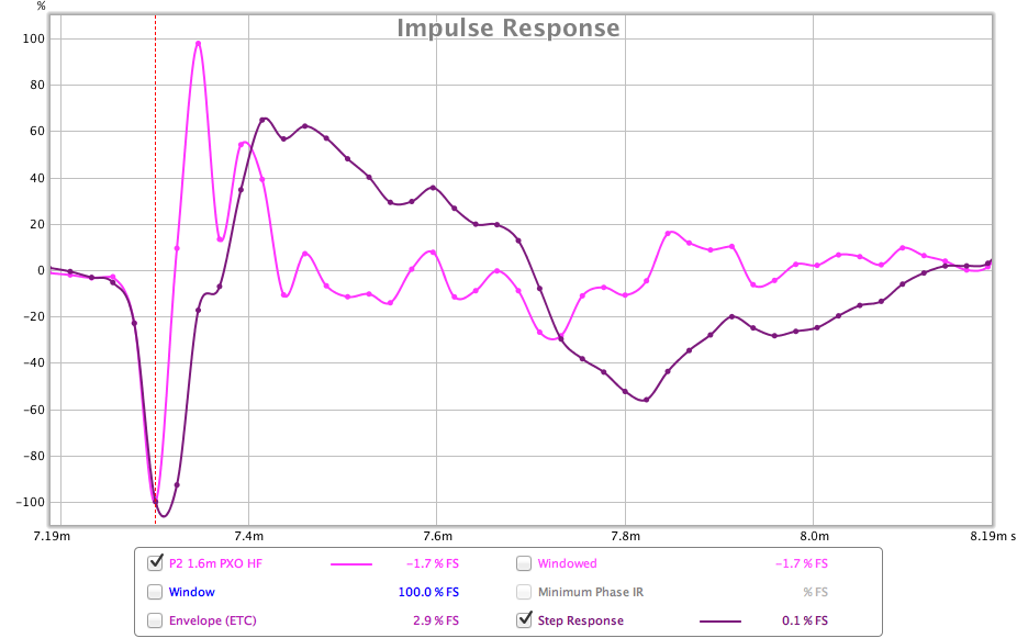
First, we're interested in the individual driver impulse response with the cross over filter enabled:
*no delays or EQs applied, just the crossover (But24 @ 840 Hz LP for the woofers, But48 @878 Hz HP for the HF driver)
Proto 1:
Legend: P1 = prototype #1; 1.6m = measured @ 1.6 m; XO = active crossover enabled; full = full system; LF = only the woofers playing; HF = only the HF driver playing; ext = with horn extender added; PXO = passive crossover.
Looks like the HF driver is just a little bit behind the woofers and could use a delay of about 250 microseconds, right?
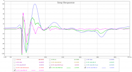
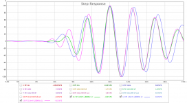
The step response for the same measurement says timing is alright, right?

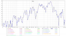
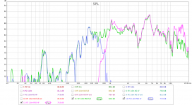
But there is a big dip at the crossover frequency...
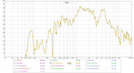
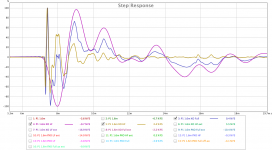
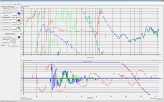
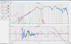
Proto 2:
...not sure what to make of it
...Timing still looks ok, right?
Yay, no dip in the crossover region
Attachments
-
 IMG_1789 small.jpeg394.3 KB · Views: 665
 -
 IMG_1792 small.jpeg173.7 KB · Views: 677
 -
 IMG_1805 small.jpeg393.1 KB · Views: 665
 -
 REW P2 SPL.png71.5 KB · Views: 648
 -
 REW P2 Step.png83.3 KB · Views: 644
 -
 REW P2 IR.png75.6 KB · Views: 648
 -
 REW P1 SPL.png82.7 KB · Views: 651
 -
 REW P1 Step.png87.6 KB · Views: 649
 -
 REW P1 IR.png88.4 KB · Views: 643
Getting smooth phase through your crossover region would be a priority for me.
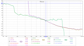
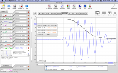
Let's have a look at the phase (after I removed the delay in REW, all IRs moved by 7.292 ms).
Here is the phase response of the second prototype (which I think is better than the first proto):
And unwrapped:
Looks to me that's all good
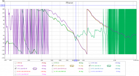
. Or isn't it? Am I correct when I think this looks like a passive crossover is still a good option?Since I still had my passive crossover laying around, I also took some measurements with it:
(On Proto #2)
Looking at the crossover region, that's not too shabby, isn't it? Am I correct when I think this looks like a passive crossover is still a good option?
Attachments
Last edited:
Nice job! I like the looks of the 2nd proto.
I think the crux of the issue is understanding the woofer IR. What is the true IR peak, whose start you want to align the CD with? That is a curious stretched out IR with a tall central peak flanked by negative peaks and some pre-ringing.
You have been aligning on that that first negative peak which suggests a polarity inversion. That first negative peak might also be pre-ringing. Consider that the bigger positive peak further out might be the true peak. Do a trial alignment on where it starts up and see what you get.
What still confuses me is finding the true start point when there is pre ringing. Is it where it starts up from the most negative point or where it crosses zero on the way up? That requires an empirical answer.
Jack
I am finding it difficult to follow the graphs, perhaps too many colours and traces together.
I agree that it is weird that you get a negative peak before a larger positive one and that the positive one is the true peak.
Another thing that you can do is to filter the IR with a 1/3 Octave filter at or around the crossover point. That can make it easier to see if the traces line up there.
The phase in the later graphs does look to track pretty well particularly above the crossover point. I'm not sure which ones are which as I need to view them on a bigger screen.
ThanksNice job! I like the looks of the 2nd proto.
I think the crux of the issue is understanding the woofer IR. What is the true IR peak, whose start you want to align the CD with? That is a curious stretched out IR with a tall central peak flanked by negative peaks and some pre-ringing.
. The true IR peak... It looks like there is an inversion somewhere in my chain, I've noticed this before. So I guess it would be the first negative peak. But then it's odd that the first positive peak is bigger than the first negative peak . If anyone has any idea what is going on here, please speak up .Maybe it might be a good idea to try a different amp and see if the picture is reversed.You have been aligning on that that first negative peak which suggests a polarity inversion. That first negative peak might also be pre-ringing. Consider that the bigger positive peak further out might be the true peak. Do a trial alignment on where it starts up and see what you get.
Ok, so it's not just me who is confusedWhat still confuses me is finding the true start point when there is pre ringing. Is it where it starts up from the most negative point or where it crosses zero on the way up? That requires an empirical answer.
.During the same measurement session I also measured with HOLM's Square Noise (improved MLS) measurement signal (on a different system). Here are some results.
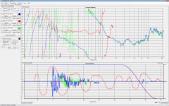
Proto #2 with active crossover and horn extender:
I set the window at about 2.75 m, as there seems to be a reflexion at 2.90 m. There is a slight dip in SPL at the crossover range, but the phase seems quite smooth, although I think it looks like Holm has trouble deciding the correct IR peak as well, which results in a LF phase response that might be incorrect.
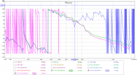
The passive crossover looks even better:
The SPL show less dip in the crossover region due to a little bit of attenuation of the 1-2k region. Phase response is quite smooth and has 360 degrees less turning in the 400-1k Hz region.
Attachments
I'm not sure whether I get what you meanAnother thing that you can do is to filter the IR with a 1/3 Octave filter at or around the crossover point. That can make it easier to see if the traces line up there.
. I went to the Filtered IR tab and selected 800Hz 1/3 for all three PXO measurements (LF, HF and full). Is that what you mean? This results in the following IRs:
And step response:
Attachments
I'm not sure whether I get what you mean
Yes that is what I meant
You can use frequencies around the crossover to see what is happening. The closer the wave shapes fit on top of each other the better the tracking is at the crossover. Choosing a higher or lower filter frequency will show how well it tracks further out from the crossover point.
You could use a small delay to see if you can line them up even closer. Concentrate on the middle of the graph to get the best match, then see if your other measurements are better.
Can you make an impulse and step graph with just the compression driver and nothing else?
That is good to know! Thanks!You can use frequencies around the crossover to see what is happening. The closer the wave shapes fit on top of each other the better the tracking is at the crossover. Choosing a higher or lower filter frequency will show how well it tracks further out from the crossover point.
Looking at the last two graphs I would say they're already quite close in the middle. Or am I seeing it wrong?You could use a small delay to see if you can line them up even closer. Concentrate on the middle of the graph to get the best match, then see if your other measurements are better.
Can you make an impulse and step graph with just the compression driver and nothing else?
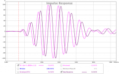
Sure! Here is filtered with 800Hz 1/3:
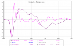
And here is unfiltered:
Attachments
No problem just passing on something I saw wesayso suggest as it seemed relevant to this.That is good to know! Thanks!
Yes they look close which makes sense as your phase looked close. I meant more if you wanted to use an all pass or delay to get the time alignment spot on.Looking at the last two graphs I would say they're already quite close in the middle. Or am I seeing it wrong?
Sure! Here is filtered with 800Hz 1/3:

And here is unfiltered:
Hmm that is a weird response. I really cannot tell if there is a polarity inversion or something else. What is the time between the negative and positive peaks ? Work that out as a distance and see if there is anything in the horn throat that corresponds to that distance.
You could also try and plug the ports of the woofer and tape over to see if they are affecting the response.
The time between the sharp positive and negative peaks in the IR is 46 microseconds. That would translate to ~1.6 cm.Hmm that is a weird response. I really cannot tell if there is a polarity inversion or something else. What is the time between the negative and positive peaks ? Work that out as a distance and see if there is anything in the horn throat that corresponds to that distance.
You could also try and plug the ports of the woofer and tape over to see if they are affecting the response.
The only thing in the horn that is around that size is the width of the entry ports for the woofers at a certain distance, as they very in width, as you have probably seen in the photos. The shortest distance between the ports is about 3 cm (the sides of the horn wall). I will look into the apparent phase inversion and maybe try to plug the ports and see if that is where this comes from, although there would be no real solution then...
The time between the sharp positive and negative peaks in the IR is 46 microseconds. That would translate to ~1.6 cm.Hmm that is a weird response. I really cannot tell if there is a polarity inversion or something else. What is the time between the negative and positive peaks ? Work that out as a distance and see if there is anything in the horn throat that corresponds to that distance.
You could also try and plug the ports of the woofer and tape over to see if they are affecting the response.
The only thing in the horn that is around that size is the width of the entry ports for the woofers at a certain distance, as they vary in width, as you have probably seen in the photos. The shortest distance between the ports is about 3 cm (the sides of the horn wall). I will look into the apparent phase inversion and maybe try to plug the ports and see if that is where this comes from, although there would be no real solution then...
The only other way I can think of to find out the polarity of your CD is to do a crossover test. By checking a simulation against what you have. If the crossover is meant to be both positive in phase then by reversing the woofers there should be a null or vice versa if the crossover was designed to have the drivers out of phase. Check the woofers polarity with a battery or positive pulse so you are certain you have that right. When you know the polarity of your CD from the measurement then you can work out if it is pre or post.
You could also do a low level test of your CD outside of the horn to see if it is the same.
You could also do a low level test of your CD outside of the horn to see if it is the same.
It's been a while since I updated this thread. I had a few things important to take care of. But here's where I am now...
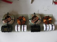
After realising I couldn't buy a separate amp of decent quality for the CD and go active for the price of the crossover components, I chose to stay on the passive path. I decided on 3rd order for the CD and 2nd order for the woofer section. After trying different values I settled for 10uF - 1.5mH - 10uF for the CD and 0.82mH - 47uF for the woofer section. This configuration resulted in 'fairly' flat phase and frequency responses through the crossover range without any amp killing impedance dips. EQ was going to be needed, but that is nothing new in the PA world.
I still needed to shift the bass reflex port tuning up from 80-ish to 100-ish, so I filled some corners and cavities of the cabinet with PU construction foam. To make the enclosure any smaller is not really an option, as it would be near impossible to get the drivers in or out of the cabinet. Maybe it is possible, but I didn't feel like starting all over again .
.
Photos will follow.
I did some comparison measurements between my DR200 tops (Bill Fitzmaurice design) and my 'Synergy B'. Measurement was with 1V @ 50Hz input, no filters, no EQ, measured @ 160 cm. Settings were unchanged. I just plugged from one box to the other (2x DR200 is 2 of them in parallel) and repositioned the mic (yes, there are some room influences visible, dip at 120 Hz...).
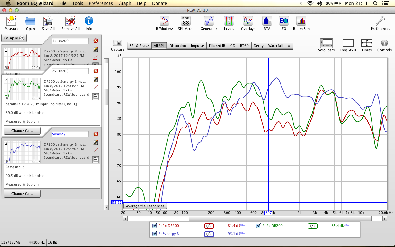
My aim was to replace 4 DR200 tops by 2 Synergy horns. More compact, better coherence and quality. I'm not really done yet, but it's going to be close (SPL wise). The DR200s are loaded with an 8 ohm Eminence Beta 8a and will take up to 225W RMS (450W program) each (so 450W RMS @ 4 ohm for two of them), while the Synergy B uses two 8 ohm B&C 12NDL76s good for 800W RMS @ 4 ohm and 1600W program @ 4 ohm. Above 800 Hz the Synergy B has the two DR200s beat, but below that you can see the unloading of the woofers having a big negative impact on SPL...
I hope to be able to do a big measurement/tuning session outside in the open somewhere end of July with most of the PA stuff I have built so far. Then I will be able to make a final conclusion.
After realising I couldn't buy a separate amp of decent quality for the CD and go active for the price of the crossover components, I chose to stay on the passive path. I decided on 3rd order for the CD and 2nd order for the woofer section. After trying different values I settled for 10uF - 1.5mH - 10uF for the CD and 0.82mH - 47uF for the woofer section. This configuration resulted in 'fairly' flat phase and frequency responses through the crossover range without any amp killing impedance dips. EQ was going to be needed, but that is nothing new in the PA world.
I still needed to shift the bass reflex port tuning up from 80-ish to 100-ish, so I filled some corners and cavities of the cabinet with PU construction foam. To make the enclosure any smaller is not really an option, as it would be near impossible to get the drivers in or out of the cabinet. Maybe it is possible, but I didn't feel like starting all over again
.Photos will follow
.I did some comparison measurements between my DR200 tops (Bill Fitzmaurice design) and my 'Synergy B'. Measurement was with 1V @ 50Hz input, no filters, no EQ, measured @ 160 cm. Settings were unchanged. I just plugged from one box to the other (2x DR200 is 2 of them in parallel) and repositioned the mic (yes, there are some room influences visible, dip at 120 Hz...).
My aim was to replace 4 DR200 tops by 2 Synergy horns. More compact, better coherence and quality. I'm not really done yet, but it's going to be close (SPL wise)
. The DR200s are loaded with an 8 ohm Eminence Beta 8a and will take up to 225W RMS (450W program) each (so 450W RMS @ 4 ohm for two of them), while the Synergy B uses two 8 ohm B&C 12NDL76s good for 800W RMS @ 4 ohm and 1600W program @ 4 ohm. Above 800 Hz the Synergy B has the two DR200s beat, but below that you can see the unloading of the woofers having a big negative impact on SPL...I hope to be able to do a big measurement/tuning session outside in the open somewhere end of July with most of the PA stuff I have built so far. Then I will be able to make a final conclusion.
Attachments
Last edited:
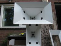
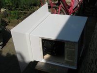
As promised, some photos
Attachments
-
 IMG_1783 small.JPG115.7 KB · Views: 484
 -
 IMG_1815 small.JPG147 KB · Views: 240
 -
 IMG_1814 small.JPG139.6 KB · Views: 243
 -
 IMG_1811 small.JPG125.6 KB · Views: 248
 -
 IMG_1806 small.JPG146.8 KB · Views: 242
 -
 IMG_1794 small.JPG124.7 KB · Views: 209
 -
 IMG_1790 small.JPG142.9 KB · Views: 216
 -
 IMG_1788 small.JPG111.1 KB · Views: 212
 -
 IMG_1786 small.JPG114.5 KB · Views: 187
 -
 IMG_1782 small.JPG207.2 KB · Views: 227
More...
Attachments
-
 IMG_1832 small.JPG127.3 KB · Views: 207
 -
 IMG_1831 small.JPG130.5 KB · Views: 188
 -
 IMG_1828 small.JPG112.8 KB · Views: 148
 -
 IMG_1827 small.JPG78 KB · Views: 145
 -
 IMG_1824 small.JPG149.8 KB · Views: 161
 -
 IMG_1823 small.JPG87.9 KB · Views: 175
 -
 IMG_1822 small.JPG173.2 KB · Views: 169
 -
 IMG_1821 small.JPG65.9 KB · Views: 197
 -
 IMG_1818 small.JPG125.2 KB · Views: 204
 -
 IMG_1817 small.JPG166.4 KB · Views: 220
- Status
- This old topic is closed. If you want to reopen this topic, contact a moderator using the "Report Post" button.
- Home
- Loudspeakers
- Multi-Way
- Synergy horn for 135 dB+