The nicer units are plug and play and literally appear as a printer in windows and you print from Solidworks etc via STL file. Sounds like you got a DIY type of machine and not a corporate engineering model.
The thing that really spooked me is that some of these printers require proprietary filament. That's the same scam that HP has been running for years. HP is one of my investments, and if you ever wants some lulz, take a look at their financials. It's *astounding* how much money a company can make when they give the printers away and gouge you for the ink. HP has made me a lot of money.
So the main reason that I went for the printrbot was that it works with open source software, and it doesn't use proprietary filament.
But, yeah, it is a royal p.i.t.a. to get it working. Here's a review from Amazon that's consistent with my experience:
Don't buy this if you don't have a degree in engineering. It is not a turnkey unit. I have spent over a month now trying to get it to work and I have not got one item to print. I am a member of Mensa and have a master's degree. I bet I have watched 20 hours or videos (it doesn't come with a manual). I finally bought a heated bed because I thought that would help. I spent 4 hours installing it and found that the electrical wiring (for which there are no instructions) doesn't look anything like the wiring in the video they posted to show you how to hook up the electrical connections. If you want to print 3D without spending a year getting the machine set up buy a Cube 3D. I have read that it is actually ready to use when you buy it.
Ironically, I'm actually fairly happy with the device at this point. It *did* require four hours to get it working, but it IS working now. Then again, what's your time worth? It may have been wiser to step up to a $1000 unit on the hope that it actually works out-of-the-box.
Cookiemonster do you have this STL hosted somewhere? I'd love to look into printing a pair of these myself possibly.
I have a 3D printing company and would be happy to talk with anyone who is interested in having something printed through PM. That local PLA quote you received actually isn't bad. Printing something of this size takes time.
I am currently working on a 3D printer kit that I hope to release sometime this year and have been working in the 3D printing space about 2 years now. I have some great ideas on how 3D printing is going to push speaker and circuit board design way forward. For now the speaker part is accessible, and I think we will start seeing a dramatic shift in DIY speakers in the next few years. One project I would like to do is to print a back loaded horn with a very low diffraction body. I potentially have access to a printer that could do something like this as long as it was under 2'X2'X3' but I do not have the modeling chops to design it myself.
Last edited:
Figuring out how to make an oblate spheroidal(ish) waveguide that's pyramid shaped took some trial and error.
Here's what I did:
First, you have to make a pyramid. This literally takes five seconds. Here's how to do it:
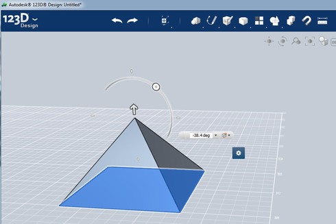
pyramids with 123D Design?
Your pyramid will have a point, and that's not going to work. (There's no entry for the compression driver.)
Due to that, I sketch out the pyramid in 2D, and figure out how much of the top has to be lopped off in two dimensions. For instance, in my pyramid, I had to lop off the top 29mm.
Once you know how much to lop off, make a cube, and make it intersect with your pyramid. Then select the "combine" option that subtracts one shape from the other.
Voila! You now have a pyramid with the top missing.
The entry for the compression driver is now square. You have to fix that. Changing the entry to a circle is actually quite easy. You just "filet" the edges of the shape. The shape above isn't mine - it's from the 123D website. The website will show you how filet works.
There are a few ways to do the oblate spheroidal part. Ideally, you would do a spline that joins the exit of the compression driver to the entrance of your horn.
I "cheated." I took the coverage angle of my waveguide, and the exit angle of my compression driver, and averaged them. For instance, if your compression driver has an exit of twenty degrees, and your waveguide has a coverage of forty, you would use a thirty degree angle for the piece that joins the two.
This isn't 100% accurate, but it's definitely better than having an abrupt transition at the exit of the throat.
The connecting piece for the throat, the one that reduces diffraction, is made the exact same way you make the pyramid. It takes five seconds. The difference is that you start with a circle and extrude it to a partial cone, instead of starting with a square and extruding it to a partial pyramid.
Here's what I did:
First, you have to make a pyramid. This literally takes five seconds. Here's how to do it:
pyramids with 123D Design?
Your pyramid will have a point, and that's not going to work. (There's no entry for the compression driver.)
Due to that, I sketch out the pyramid in 2D, and figure out how much of the top has to be lopped off in two dimensions. For instance, in my pyramid, I had to lop off the top 29mm.
Once you know how much to lop off, make a cube, and make it intersect with your pyramid. Then select the "combine" option that subtracts one shape from the other.
Voila! You now have a pyramid with the top missing.
An externally hosted image should be here but it was not working when we last tested it.
The entry for the compression driver is now square. You have to fix that. Changing the entry to a circle is actually quite easy. You just "filet" the edges of the shape. The shape above isn't mine - it's from the 123D website. The website will show you how filet works.
There are a few ways to do the oblate spheroidal part. Ideally, you would do a spline that joins the exit of the compression driver to the entrance of your horn.
I "cheated." I took the coverage angle of my waveguide, and the exit angle of my compression driver, and averaged them. For instance, if your compression driver has an exit of twenty degrees, and your waveguide has a coverage of forty, you would use a thirty degree angle for the piece that joins the two.
This isn't 100% accurate, but it's definitely better than having an abrupt transition at the exit of the throat.
The connecting piece for the throat, the one that reduces diffraction, is made the exact same way you make the pyramid. It takes five seconds. The difference is that you start with a circle and extrude it to a partial cone, instead of starting with a square and extruding it to a partial pyramid.
Here is how I do the pyramid in Sketchup. It might work in 123D as well and eliminate that manual figuring out part.
Get the mouth dimensions and depth from Bill Waslo's spreadsheet based on the coverage angles and pattern control frequency.
Draw a rectangle with the mouth dimensions.
Push/pull (extrude) the rectangle to the horn depth.
Draw a CD entry sized square at the center of the back wall of the horn box.
Connect the corners of that square to the corners of the face of the box that represents the mouth of the horn.
You have your conical horn.
Make each wall of the horn a component, push/pull it to the desired thickness, intersect faces and trim off the overlap to create the joints (its not really that easy but that is the general idea)
Jack
Figuring out how to make an oblate spheroidal(ish) waveguide that's pyramid shaped took some trial and error.
Here's what I did:
First, you have to make a pyramid. This literally takes five seconds. Here's how to do it:
pyramids with 123D Design?
Your pyramid will have a point, and that's not going to work. (There's no entry for the compression driver.)
Due to that, I sketch out the pyramid in 2D, and figure out how much of the top has to be lopped off in two dimensions. For instance, in my pyramid, I had to lop off the top 29mm.
Once you know how much to lop off, make a cube, and make it intersect with your pyramid. Then select the "combine" option that subtracts one shape from the other.
Voila! You now have a pyramid with the top missing.
An externally hosted image should be here but it was not working when we last tested it.
The entry for the compression driver is now square. You have to fix that. Changing the entry to a circle is actually quite easy. You just "filet" the edges of the shape. The shape above isn't mine - it's from the 123D website. The website will show you how filet works.
There are a few ways to do the oblate spheroidal part. Ideally, you would do a spline that joins the exit of the compression driver to the entrance of your horn.
I "cheated." I took the coverage angle of my waveguide, and the exit angle of my compression driver, and averaged them. For instance, if your compression driver has an exit of twenty degrees, and your waveguide has a coverage of forty, you would use a thirty degree angle for the piece that joins the two.
This isn't 100% accurate, but it's definitely better than having an abrupt transition at the exit of the throat.
The connecting piece for the throat, the one that reduces diffraction, is made the exact same way you make the pyramid. It takes five seconds. The difference is that you start with a circle and extrude it to a partial cone, instead of starting with a square and extruding it to a partial pyramid.
This was covered in a rigorous fashion by Hulkss in post 990 of "Suitable midrange cone..." it is more complicated than you think to get a Hughes profile.
http://www.diyaudio.com/forums/multi-way/88237-suitable-midrange-cone-bandpass-mid-unity-horn-99.html#post3529953
What I have found works well is to use non-hardening oil/plastic modeling clay to fill in the corners and shape it until it looks smooth and the measurements show a smooth response.
If anyone wants to mess around with what I came up with, or even print it, here's the model in STL format:
https://mega.co.nz/#!0BZSgTrL!IY5UjC5gbDchZhg89wQhaAOoB9WZvzKEMbfaLiTs2_0
Here's the model in 123D format. (Much much smaller file.)
https://mega.co.nz/#!YYgWACwR!lxvizFz8Bj3vICgQv-czdqy42Cxv5x2UFuW7qkBGw7Y
If you want to build it, here's what you'll need:
1) some way to print in 3D. (Shapeways?)
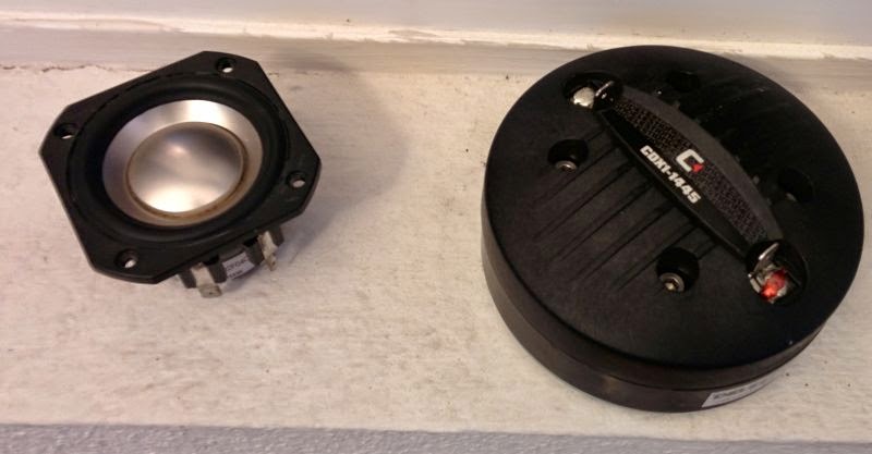
2) two or four Peerless 830970s. $40-$80
3) A Celestion CDX1-1445 $45 Celestion CDX1-1445 Ferrite 1" Compression Driver 20W
$10 worth of crossover parts should get you in the ballpark. Or better yet, spend $120 and get a miniDSP and a chip amp.
So that's about $150-$200 per side for drivers, xovers, and possibly amplification. The cost of 3D printing will depend on how much of the waveguide you use. If it were me I'd only print the first three inches or so, and make the rest out of wood. I've found that building the first three inches is the tricky part.
That 1445 CD specs recommend 2.2khz xo. Can those Peerless in those bandpass injection holes reach that high? I seem to recall 1khz being tough.
I cross my compression drivers at 20khz.
When you combine a first order low pass at 20khz with the naturally falling response of a compression driver, you wind up with flat response. At 1250hz they're down 24dB (due to the first order filter.)
You basically wind up with a driver that has flat response from 1500hz to 20khz, with an output of about 85dB.
Of course, 85dB doesn't sound like much, but keep in mind that due to the passive filter, they're only getting about a hundredth of a watt to produce 85dB at 1250hz.
This type of filter would be impractical for prosound, because it's a waste of amplifier power. And not practical for tubes, for the same reason. But for solid state home hifi it works great.
Last edited:
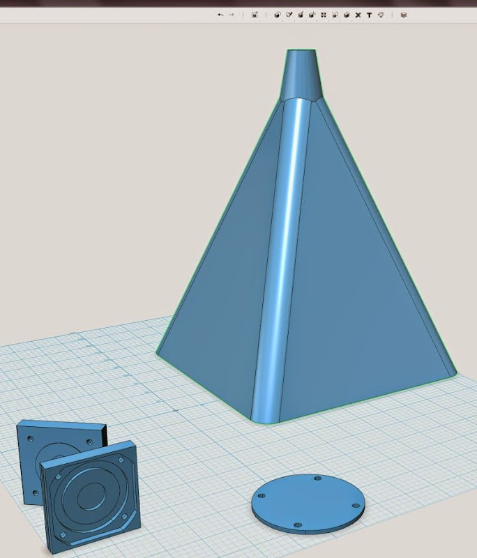
Here's a version with the midrange taps added and the midrange mounting plates attached.
This is what I'm going to try and print tonight:
https://mega.co.nz/#!9JZ2HYBR!SX-f67F7OG3Fo8mWVgE-KkXFFAacpiu5LGhcYk-YIxk
(in STL format.)
This is what I'm going to try and print tonight:
https://mega.co.nz/#!9JZ2HYBR!SX-f67F7OG3Fo8mWVgE-KkXFFAacpiu5LGhcYk-YIxk
(in STL format.)
Impressive progress!
I was (ironically) able to open and view the file in Aspire Trial Edition, typically used for CNCing. It would be folly to try and CNC it but individual pieces certainly could be done that way. OTOH, a 3D printer is way cheaper and smaller than an CNC router.
I was (ironically) able to open and view the file in Aspire Trial Edition, typically used for CNCing. It would be folly to try and CNC it but individual pieces certainly could be done that way. OTOH, a 3D printer is way cheaper and smaller than an CNC router.
Attachments
Cookiemonster do you have this STL hosted somewhere? I'd love to look into printing a pair of these myself possibly.
I have a 3D printing company and would be happy to talk with anyone who is interested in having something printed through PM. That local PLA quote you received actually isn't bad. Printing something of this size takes time.
I am currently working on a 3D printer kit that I hope to release sometime this year and have been working in the 3D printing space about 2 years now. I have some great ideas on how 3D printing is going to push speaker and circuit board design way forward. For now the speaker part is accessible, and I think we will start seeing a dramatic shift in DIY speakers in the next few years. One project I would like to do is to print a back loaded horn with a very low diffraction body. I potentially have access to a printer that could do something like this as long as it was under 2'X2'X3' but I do not have the modeling chops to design it myself.
I will certainly share it as long as there is no intention to use it for anything but DIY. However, i have not yet revisited the midrange choice. I think the comments I have received by others here make me think it might be beneficial to go for a variant that can dig a bit deeper, and perhaps one where I can adjust the rear cavity. So I will not fine tune the model using the M10. It´s been rather busy lately, with some home projects and work getting in the way - but I´ll see if I can pick up that part of it this weekend, trying to sim a different driver and modeling the right STL file for it.
I might take you up on your offer to print my model later too - let me just get it completed. Perhaps you can help us understand the limitations in printing slopes etc? I was trying to avoid overhangs more than 45 degrees - does this apply to all 3D printers, for instance?
Offset port vs centered port - woofer example in ABEC
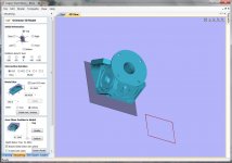
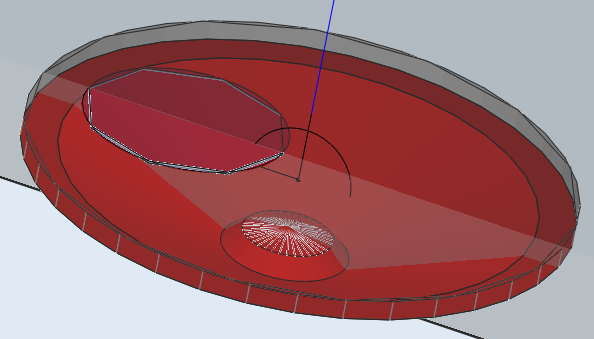
I got sidetracked from the midrange bit because I wanted to experiment with ABEC3 on the effect of having the output ports offset from the center of the driver. In the M10 example, I went to some trouble to keep the ports centered in a frustum to get minimal cancellation of sound waves. I don´t think Akabak simulates this, and I suspect it could lead to frustration when trying to get mids to "reach high" if one is not aware of the effect of the offset ports.
I did a very simple example, based on the 10CL51 driver from the Synergy Tripp thread. The reason I used that one was because somebody had posted a nice profile of the cone interior, so I could get a pretty accurate model in ABEC. Not 100%, but good enough.
So in the simple model, I have used the following Akabak-paramters, if somebody wants to validate:
Def_Driver "10CL51"
Re=5.2ohm Le=0.8mH
| Rg=0
fre=1kHz ExpoRe=0.8 ExpoLe=1.6
Mms=32.321g Cms=0.218e-3m/N Rms=3.206Ns/m Bl=12N/A
Bl=12N/A Mms=32.321g Cms=0.218e-3m/N Rms=3.206Ns/m
| fs=60Hz Qms=3.8 Qes=0.44
The script is BEM except for the rear of the cone, which goes into a LEM enclosure of 60L. Huge yes, but it was just what I put in to make the bottom end as smooth as possible. No vents of anything. Low frequency is not really the interest here, as it doesn´t matter for this purpose anyway. There simulation uses an infinite baffle, so no wrap-around etc (imagine the driver mounted on a huge wall - no floors, ceilings etc).
First, the response from 1m @ 2.83VRMS with a 100mm hole centered. 100mm is chosen randomly. Unfortunately, once you go "full BEM", I can´t find a way to measure flow velocity through a port.
(Perhaps xrk971 could help with the ideal port size for this woofer? I thought I had found it as 1.68 square inches in the Synergy Tripp thread - is that correct? Two exits per woofer? I don´t mind using that woofer as there is a proof of concept in the Synergy Tripp thread, but for the heck of it i´d also like to use mids - more learning (and frustration probably) for me, but that´s why we do this..") )
)
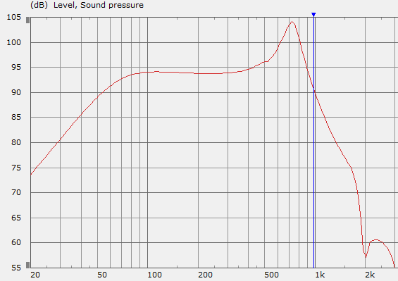
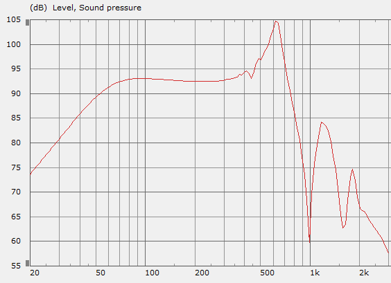
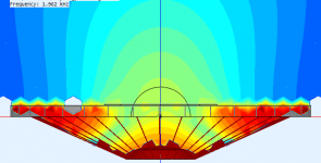
Anyhow, the sim is interesting - so first with a centered hole:
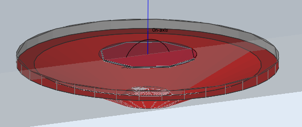
One can clearly see a a peak and a deep dip following, as can be expected, at around 2000hz.
The found field at 2000Hz looks like this:
There is a neat cancellation of the soundwaves coming from the left and right, leaving us with (probably very simplified) with the sound from the middle of the cone.
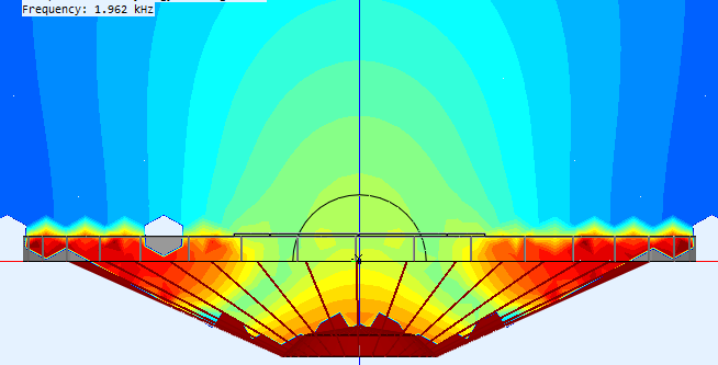
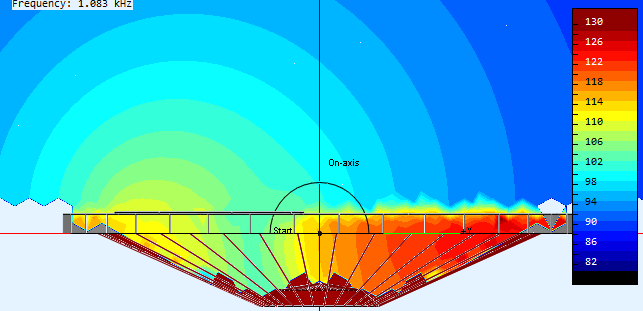
Moving on to the offset variant (60 mm offset)- no phase plug or anything here:
The peak appears a bit lower in frequency, sharper, and is followed by a strong peak/dip pattern, with the first dip at 1000hz instead of 2000hz. An octave!
Examining the sound field for the 1000hz dip, one can see how the sound waves from the right side arrives at the left side (where the port is) such that the two cancel out.
It seems to me like its worth striving for centered entry if one wants to extend high frequency response. Even better than the simple hole would probably be some kind of phase plug - depending on how high one wants to go in frequency. Cone breakup will be an issue, and is one of the reasons why I´d like to use mids rather than make a big deal with trying to extend the highs of the woofers.
With an octave difference in this example, it won´t be unreasonable to expect similar effects with the mids. Tuning the entry to get the desired extension is important.
I would like to run the example with parameters from the mids you guys have suggested.
xkr971: perhaps you could make a paper cutout of the cone profile for the B&C 6MDN44 and I could try to see how it models with offset/centered/centered frustum/offset frustum variations?
I got sidetracked from the midrange bit because I wanted to experiment with ABEC3 on the effect of having the output ports offset from the center of the driver. In the M10 example, I went to some trouble to keep the ports centered in a frustum to get minimal cancellation of sound waves. I don´t think Akabak simulates this, and I suspect it could lead to frustration when trying to get mids to "reach high" if one is not aware of the effect of the offset ports.
I did a very simple example, based on the 10CL51 driver from the Synergy Tripp thread. The reason I used that one was because somebody had posted a nice profile of the cone interior, so I could get a pretty accurate model in ABEC. Not 100%, but good enough.
So in the simple model, I have used the following Akabak-paramters, if somebody wants to validate:
Def_Driver "10CL51"
Re=5.2ohm Le=0.8mH
| Rg=0
fre=1kHz ExpoRe=0.8 ExpoLe=1.6
Mms=32.321g Cms=0.218e-3m/N Rms=3.206Ns/m Bl=12N/A
Bl=12N/A Mms=32.321g Cms=0.218e-3m/N Rms=3.206Ns/m
| fs=60Hz Qms=3.8 Qes=0.44
The script is BEM except for the rear of the cone, which goes into a LEM enclosure of 60L. Huge yes, but it was just what I put in to make the bottom end as smooth as possible. No vents of anything. Low frequency is not really the interest here, as it doesn´t matter for this purpose anyway. There simulation uses an infinite baffle, so no wrap-around etc (imagine the driver mounted on a huge wall - no floors, ceilings etc).
First, the response from 1m @ 2.83VRMS with a 100mm hole centered. 100mm is chosen randomly. Unfortunately, once you go "full BEM", I can´t find a way to measure flow velocity through a port.
(Perhaps xrk971 could help with the ideal port size for this woofer? I thought I had found it as 1.68 square inches in the Synergy Tripp thread - is that correct? Two exits per woofer? I don´t mind using that woofer as there is a proof of concept in the Synergy Tripp thread, but for the heck of it i´d also like to use mids - more learning (and frustration probably) for me, but that´s why we do this..
)Anyhow, the sim is interesting - so first with a centered hole:
One can clearly see a a peak and a deep dip following, as can be expected, at around 2000hz.
The found field at 2000Hz looks like this:
There is a neat cancellation of the soundwaves coming from the left and right, leaving us with (probably very simplified) with the sound from the middle of the cone.
Moving on to the offset variant (60 mm offset)- no phase plug or anything here:
The peak appears a bit lower in frequency, sharper, and is followed by a strong peak/dip pattern, with the first dip at 1000hz instead of 2000hz. An octave!
Examining the sound field for the 1000hz dip, one can see how the sound waves from the right side arrives at the left side (where the port is) such that the two cancel out.
It seems to me like its worth striving for centered entry if one wants to extend high frequency response. Even better than the simple hole would probably be some kind of phase plug - depending on how high one wants to go in frequency. Cone breakup will be an issue, and is one of the reasons why I´d like to use mids rather than make a big deal with trying to extend the highs of the woofers.
With an octave difference in this example, it won´t be unreasonable to expect similar effects with the mids. Tuning the entry to get the desired extension is important.
I would like to run the example with parameters from the mids you guys have suggested.
xkr971: perhaps you could make a paper cutout of the cone profile for the B&C 6MDN44 and I could try to see how it models with offset/centered/centered frustum/offset frustum variations?
Attachments
-
 2015-01-12 21_52_01-ABEC3 - ABEC Synergy midrange test.png54 KB · Views: 810
 -
![2015-01-12 21_53_54-VacsViewer - (new) - [SPL].png](/community/data/attachments/434/434219-0693bd0842e12cb2b5429861858cf721.jpg) 2015-01-12 21_53_54-VacsViewer - (new) - [SPL].png17.5 KB · Views: 796
2015-01-12 21_53_54-VacsViewer - (new) - [SPL].png17.5 KB · Views: 796 -
 2015-01-12 21_58_30-ABEC3 - ABEC Synergy midrange test.png33.3 KB · Views: 803
 -
 2015-01-12 22_11_59-ABEC3 - ABEC Synergy midrange test.png36.4 KB · Views: 797
 -
![2015-01-12 22_11_29-VacsViewer - (new) - [SPL].png](/community/data/attachments/434/434285-8573153396891c1baf9c0a454f194a33.jpg) 2015-01-12 22_11_29-VacsViewer - (new) - [SPL].png16.9 KB · Views: 803
2015-01-12 22_11_29-VacsViewer - (new) - [SPL].png16.9 KB · Views: 803 -
 2015-01-12 22_17_10-ABEC3 - ABEC Synergy midrange test.png34.2 KB · Views: 789

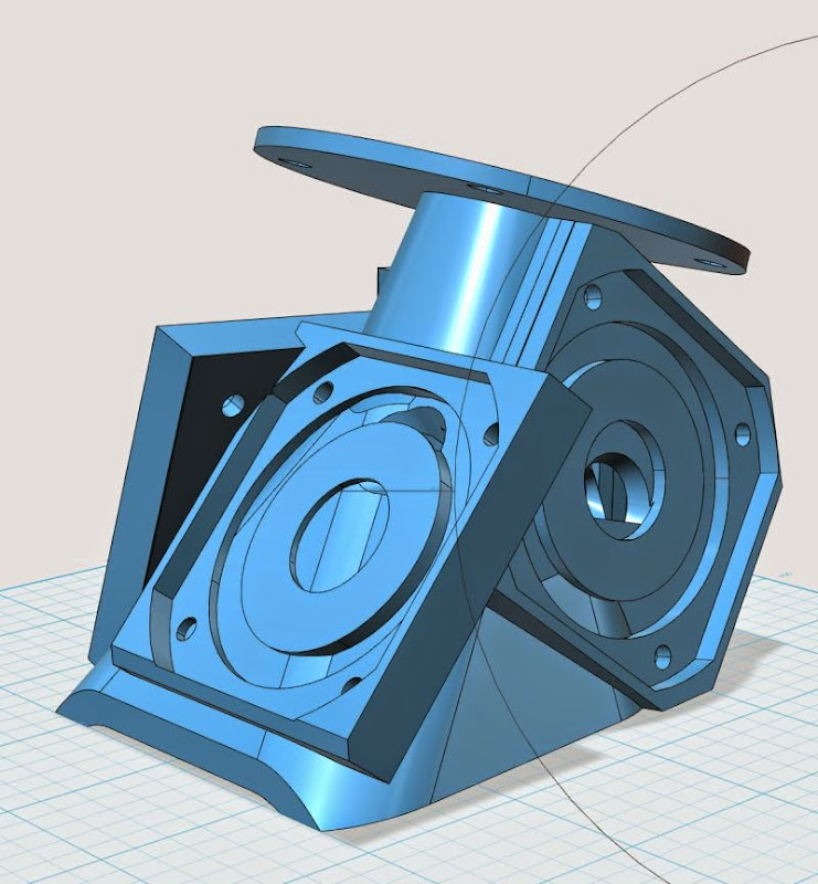
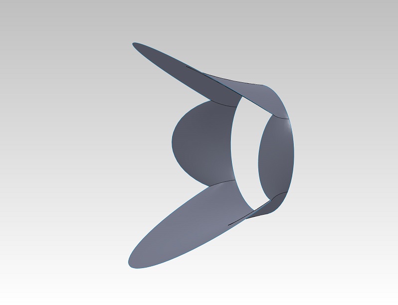
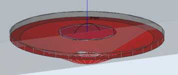
Here's the model that I posted on Mega yesterday. This is the last model I posted on Sunday night, Jan 11.
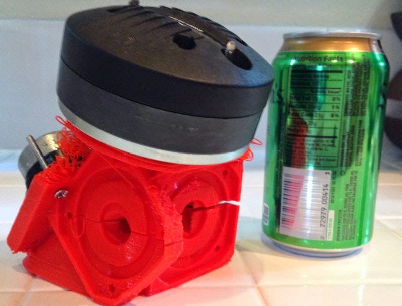

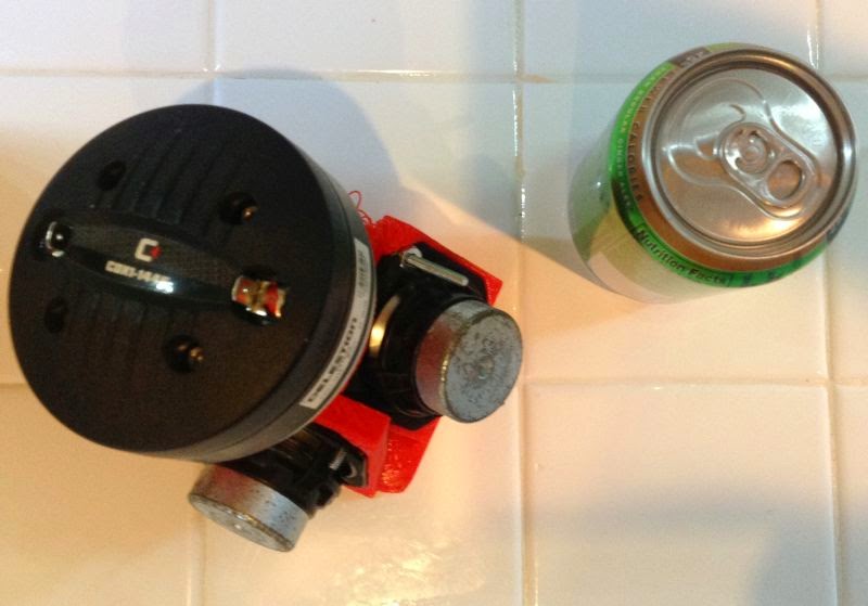
Here's the horn IRL
Here's some random observations:
1) The ability to make these weird shapes that are accurate down to fractions of a millimeter is a real game changer. Most of the horn was based on walls that are about an 1/8th of an inch thick. I could never pull that off with wood. With 3D printing, I probably could have gone a lot thinner than this! It's shocking.
2) Having the midrange mounting plates embedded into the horn body allows for really really tight spacing. I put a soda can in the picture to give an idea of the size. Honestly I think it might be possible to make this thing much much smaller. It has a foot print of one liter; I could probably get this down to half a liter.
3) I'm starting to scheme on putting a real phase plug in front of the midranges.
4) The cost was surprisingly cheap. Under five bucks in filament. I used up one tenth of a kilogram.
4) There's plenty of downsides, unfortunately
It takes fo-rev-er to print. About twelve hours for a pair. I had to print mine in two pieces, because it "slipped" at one point during the print process. If you're not prepared to keep an eye on the print, there's a decent chance it won't print properly.Cookie:
I did the same center vs offset hole experiment in the lab with a driver mounted over a hole through a large baffle board and got the very similar results. This led me to implement what I called a "top hat" phase plug (attached). The plug is hollowed out to duct the sound from the center hole over to the edge. The internal path length ends up being 3-4 cm long which probably means it needs to be simmed and optimized.
The phase plug improved the worst of it but I'm now trying some 6" drivers that I have on hand to see if the end result is better.
Jack
Attachments
It took me about fourteen hours to figure out how to make the waveguide.
As noted in the prior post, I think it would be possible to make the size even smaller.
I think the "trick" would be to assemble the four mounting plates into a pyramid shape in 123D, then "scoop out" the parts that interfere with each other.
IE, on Sunday I made the waveguide first, and then I "bolted" the midrange mounting plates onto the waveguide. That's the logical way to build it if you're working IRL.
But since we're doing it all in 3D, we should be able to focus on the mounting plates, and aggressively subtract and intersect the plates.
Basically the idea is to "push" everything as tightly as possible. Besides making everything smaller, it also makes the waveguide stronger, as it becomes an inter-connected whole.
I think this would also open up the possibility of putting a "real" phase plug on the midranges.
I got sidetracked from the midrange bit because I wanted to experiment with ABEC3 on the effect of having the output ports offset from the center of the driver. In the M10 example, I went to some trouble to keep the ports centered in a frustum to get minimal cancellation of sound waves. I don´t think Akabak simulates this, and I suspect it could lead to frustration when trying to get mids to "reach high" if one is not aware of the effect of the offset ports.
I did a very simple example, based on the 10CL51 driver from the Synergy Tripp thread. The reason I used that one was because somebody had posted a nice profile of the cone interior, so I could get a pretty accurate model in ABEC. Not 100%, but good enough.
So in the simple model, I have used the following Akabak-paramters, if somebody wants to validate:
Def_Driver "10CL51"
Re=5.2ohm Le=0.8mH
| Rg=0
fre=1kHz ExpoRe=0.8 ExpoLe=1.6
Mms=32.321g Cms=0.218e-3m/N Rms=3.206Ns/m Bl=12N/A
Bl=12N/A Mms=32.321g Cms=0.218e-3m/N Rms=3.206Ns/m
| fs=60Hz Qms=3.8 Qes=0.44
The script is BEM except for the rear of the cone, which goes into a LEM enclosure of 60L. Huge yes, but it was just what I put in to make the bottom end as smooth as possible. No vents of anything. Low frequency is not really the interest here, as it doesn´t matter for this purpose anyway. There simulation uses an infinite baffle, so no wrap-around etc (imagine the driver mounted on a huge wall - no floors, ceilings etc).
First, the response from 1m @ 2.83VRMS with a 100mm hole centered. 100mm is chosen randomly. Unfortunately, once you go "full BEM", I can´t find a way to measure flow velocity through a port.
(Perhaps xrk971 could help with the ideal port size for this woofer? I thought I had found it as 1.68 square inches in the Synergy Tripp thread - is that correct? Two exits per woofer? I don´t mind using that woofer as there is a proof of concept in the Synergy Tripp thread, but for the heck of it i´d also like to use mids - more learning (and frustration probably) for me, but that´s why we do this..
Anyhow, the sim is interesting - so first with a centered hole:
One can clearly see a a peak and a deep dip following, as can be expected, at around 2000hz.
The found field at 2000Hz looks like this:
There is a neat cancellation of the soundwaves coming from the left and right, leaving us with (probably very simplified) with the sound from the middle of the cone.
Moving on to the offset variant (60 mm offset)- no phase plug or anything here:
The peak appears a bit lower in frequency, sharper, and is followed by a strong peak/dip pattern, with the first dip at 1000hz instead of 2000hz. An octave!
Examining the sound field for the 1000hz dip, one can see how the sound waves from the right side arrives at the left side (where the port is) such that the two cancel out.
It seems to me like its worth striving for centered entry if one wants to extend high frequency response. Even better than the simple hole would probably be some kind of phase plug - depending on how high one wants to go in frequency. Cone breakup will be an issue, and is one of the reasons why I´d like to use mids rather than make a big deal with trying to extend the highs of the woofers.
With an octave difference in this example, it won´t be unreasonable to expect similar effects with the mids. Tuning the entry to get the desired extension is important.
I would like to run the example with parameters from the mids you guys have suggested.
xkr971: perhaps you could make a paper cutout of the cone profile for the B&C 6MDN44 and I could try to see how it models with offset/centered/centered frustum/offset frustum variations?
Cookiemonster:
Fantastic study of the effects of an offset port relative to cone. This is starting to explain some things I have been noticing on my builds. I think I may be able to approximate the offset port by making the driver chamber multiple pieces of waveguides rather than one chamber. I will take a look at replicating your 10CL51 sims in akabak.
@ winslow: Thanks. Why do you think this is? Due to the resonance of the hole being at a higher frequency?
@ patrick: wow, you are really fast! my method is basically starting with a horn that includes the quadratic throat transition, adding the holes and mounting plates for one driver, and then using a circular pattern to place them around the sides, merging overlaps etc. i tend to think that a one-piece adapter is best. i really really need to get a printer, but perhaps i´ll save up for a more plug-and-play type. the nice thing is that once you have it, using it shouldn´t be a threshold due to the low cost of material.
@nc535: good to hear you got the same results. I am wondering if a simple longer frustum would do the trick. the longer the frustum, the smaller the wavelength distances for the woofer. naturally, resonance will be an issue though. one thing i thought about was basically splitting the woofer into segments (say 4 slices of a pie) by an X-shape extending down into (but not touching obviously) the cone. that should help separate the waves from each section from eachother. I´m sure there are many ways of doing this, the goal must be to do it as simple and sturdy as possible, and keep it printable.
@xrk971: Thanks! Look forward to seeing your akabak-equivalent. Is there any chance btw you could help with the cone profile of the mid driver (if you still have one?)? And also - a verification of the port size for the port(s) used for the Synergy Tripp, so I don´t have to reinvent the wheel on that one. I suppose the port size is based the smallest you could get away with without too much air velocity?
- Status
- This old topic is closed. If you want to reopen this topic, contact a moderator using the "Report Post" button.
- Home
- Loudspeakers
- Multi-Way
- Synergy horn - 3d printing entry?