Does you mean I must increase the current quicent? I think heat cause destroy my power transistor so I often bias like thatBut i think the real problem is the feedback into the biasing beeing
unstable.
I use a1013/c2383 . a970 is a small power transistor? . Buying japan transistor is easier than europ transistor . Which transistors are equivalent to bc546b/556b?And the bjts q3/q4 could have a bit higher hfe, ~100 is not much...
the bc546b/556b i use have ~300 (measured for vce ~8v).
maybe try sa970 ? It's highvoltage and has hfe of ~500.
Yes, the 2sc2240/2sa970 are smallsignaltransistors with hfe of 350-700 (BL-versions)
They are from Toshiba, and are for "low noise audio amplifier", TO-92
But ft is only 100mhz...
I think they are a good choice as they have a Vce-rating of 120v.
I think the instability is because of the feedback, and could be
better with higher bias.
Here in europe the japanese transistors are very expensive in
compare to philips. I pay 4 cent for bc546, and 40 for sa970.
Mike
Hi !
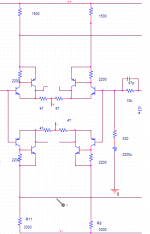
Here's my latest FC-circuit, using nested diffamps. The numbers
seem promising, i have not been able to build it as i wait for a
delivery from reichelt (ran out of resistors).
thd is ~0,0007%,OL-gain 1:27000,OL-Bandwidth -3db@27khz,
phasedelay from input to output ~100ns
What do you think ?
Mike
Here's my latest FC-circuit, using nested diffamps. The numbers
seem promising, i have not been able to build it as i wait for a
delivery from reichelt (ran out of resistors).
thd is ~0,0007%,OL-gain 1:27000,OL-Bandwidth -3db@27khz,
phasedelay from input to output ~100ns
What do you think ?
Mike
Attachments

yes .In the real circuit , I must "meet" a another bug . When I have not added two cfb transistors ,the current through Rc is equal to each another .But after I add these cfb transistors, the current through one half / another half =2Is your bug the resistors r8/11 beeing 3300 instead of 1500 ?
oh! I can know your circuit. I could not solve that bug so I think your circuit is complexI'm missing the CCS... removed for better reading ?
 .
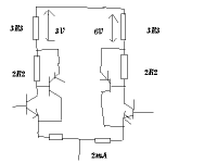
. mike! It seem to be like using the normal current source . The current source is very importance .You should use a cct with 15V zener diode .Ok! CMRR is not very normal.
In your new design, you used 2 diff stage so think CMRR is increased by many time
what do you think if R40 and R23 are replace by two cct?
Leach wrote :
"Why didn't you use current source tail supplies for the diff amps?
I had intended to use current sources in the beginning. However, when I started laying out the circuit board, I found that they added a great deal of complexity to an already dense part of the board layout. Therefore, I opted for resistive supplies to simplify the layout. I never had any problems with the resistive supplies. The amp seemed to work perfectly with them. An additional bonus is that the matching of the tail currents in the two diff amps is not a function of the matching of transistor parameters.
The turn-on characteristics of the diff amps determine the turn-on characteristics of the amplifier. With resistive tail supplies, the diff amps turn on very gracefully at a rate set by the RC time constants in the tail supply circuits. This leads to a thump free turn on, eliminating the need for output relays to protect the speakers. If transistor current source tail supplies were used, the current source transistors tend to turn on abruptly as the power supply voltages come up, which can produce thumps in the loudspeaker. This problem is even worse if one tail supply transistor turns on before the other"
http://users.ece.gatech.edu/~mleach/lowtim/faq.html
mike! have you ever used the plain resistor instead of cct?
Attachments
Yes, i used resistors instead of ccs earlier. I rejected them to have
my cicrcuit more supplyindependent. About the turnon/off-thumb,
with my symetrical circuits i have absolutely nothing audible or else.
When turning on it just begins to play, and when turning off it keeps
playing until voltage drops below ~6v, then it fades away.
The ccs can supress problems with turning on/off, as a asymetrical
powersupply does not produce DC-offset, the currents keep symetric.
The supply can become asymetrical because of caps discharging with
different speeds.
I personally prefer ccs much to the simple resistor. A normal CCS
with 2 bjts is simple to layout, it only needs one connection more
than the 1 resistor.
I layout is your problem, you should use "currentregulator-diodes",
i think they are also called tunneldiodes.
I was not able to use ccs for r40/23, the voltage is to low at this
point. But as this voltage is "constant", a resistor is enough.
It's normal with the currents beeing halfed in your circuit, the diffamp
tries to compensate the resulting DC-offset.
Mike
Hi!
I have no any objections concerning your schematics, but it seems to me that it is not the folded cascode amplifier we are talking about. I think that original idea is to build amplifier that has single stage voltage amplifier followed by output stage with high current gain. The diagram you posted has two VAS stages (the second one is folded cascode). Maybe I am not reading your diagram properly ( the influence of some dose of Yellow Tail Chardonnay from Australia on Thanksgiving Day?) Please make it clear for me if possible. Anyways circuit you posted is interesting.
Allexx
Hi Allexx !
Yes you are right, the original idea was a 2stage-classab, but i was
not happy with the sound. It had great trebles and dynamics, but
the overall sound was not ok. So i thought, ok, make a 3stage, but
with doublevas. This way i have high olgain but also high bandwidth,
giving low thd over the whole audioband. Using a folded cascode
in the 2nd stage enables the multistagetopology beeing stable and
having high bandwidth. With normal vas (4stagedesign) bandwidth
would drop inside audioband with stable settings.
Hmm, Yellow Tail Chardonnay sounds good, have you some left ?

Mike
Yes you are right, the original idea was a 2stage-classab, but i was
not happy with the sound. It had great trebles and dynamics, but
the overall sound was not ok. So i thought, ok, make a 3stage, but
with doublevas. This way i have high olgain but also high bandwidth,
giving low thd over the whole audioband. Using a folded cascode
in the 2nd stage enables the multistagetopology beeing stable and
having high bandwidth. With normal vas (4stagedesign) bandwidth
would drop inside audioband with stable settings.
Hmm, Yellow Tail Chardonnay sounds good, have you some left ?
Mike
Hi thanh !
It's not identical to my version, you changed a lot ! You changed
biasing, caps and some resistors ? I think this one will oscillate.
In my sims for 12voltswing into 4ohm 2nd harmonic is at 50uV for
1khz, and 80uV for 20khz. This is half the thd than my other symamp
at half the ol-gain.
What are your numbers ?
Mike
I've been playing around trying to improve the output stage. I've tried many variations, but the following one is the most interesting. Q8/Q7 have been added between the output of the cascode and the normal output stage. It started off as a current-source loaded emitter follower, but then it occured to me that the otherwise unused other side of the cascode is effectively a current source, but one that varies with the signal. Thus the circuit you see attached.
Attachments
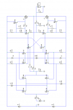
I'm not sure I understand exactly what's going on here. I'm sure it shouldn't really work at all, but it does, if slightly strangely. I somehow get the feeling it would be different in real life.
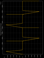
For instance, as drive to the base of Q8 increases, so the current available at its emitter from Q10 decreases. At some point, the current drops to zero and Q8 can no longer operate and so the output stage turns off. This can be seen in the following graph of what is supposed to be a sine wave driven hard into clipping.
Below clipping, and a short way above, the circuit behaves more normally, and actually shows significantly lower distortion than the previous incarnation, along with greatly reduced output impedance and a few other improved characteristics.
Attachments
Hi, Mike,
You've transformed simple idea into complex cct
I've never seen configuration like this. The Upper Folded cascode VAS Q10 is fed by lower differential Q8-Q18 and vice versa for Q11. Really interesting.
What have you got with that complex cct? Better sound or better measurement?
In other thread (which you participate) there's a hot issue about PIM, Open loop choices ie: low bandiwith+high gain VS high bandwith+low gain. It seems various opinions about this issue.
Which do you prefer from your experiments (for better sounding offcourse)?
Also it is said that big signal is not good for differential. That leads to differential with high gain. CFP differential is good?
Hi lumanauw !
Hmm, what i prefer: low thd+high OL-bandwidth+low OL-gain...
I haven't build the complex one yet, yesterday i converted my FC-prototype
into cascoded vas, as this was a "simple" change. This circuit combines
all 3 qualities i mentioned above. I can't say much about sounding yet,
DC-offset is about 400mv, too much to connect my "good" speakers.
But what i've already heard with my testspeaker was very promising.
Crystalclear, clean, and very dynamic. Even more dynamic than my FC.
THD of this cct is ~0.003%, olbw -3db @ 33khz,olgain 1:4800.
I would say, high openloopbandwidth is the key to detailed/dynamic
sound. It seems to me that low thd is quite important, but i think it
does not make sense to push it below 0.001%. Low ol-gain is always
good for stability. I can say more if this amp is connected with my
good speakers to make some serious listeningtests.
Cascoded vas with extra rload seems to be perfect for low thd with
low ol-gain. Without this extra rload it has incredible high gain, pushing
olgain up to 1:1.000.000 ! (and olbw down to -3db@200hz)
Ah, i think higher RE's enable larger signals for diffamps, in my
above mentioned amp i use 22ohms. Seems no problem in this case.
I canceled CFP-input for me, it's seems too slow compared to it's
benefits. But needs more testing...
Mike
Maybe you should put C in the feedback voltage divider. I notice you never use it in your designs. It will reduce DC offset very much.DC-offset is about 400mv
You cannot get high OL bandiwith with CFP differential?I canceled CFP-input for me, it's seems too slow compared to it's benefits
Back to your complex design. Is there any advantage by having upper VAS drived by lower differential pair vice versa?
lumanauw said:
Maybe you should put C in the feedback voltage divider. I notice you never use it in your designs. It will reduce DC offset very much.
You cannot get high OL bandiwith with CFP differential?
Back to your complex design. Is there any advantage by having upper VAS drived by lower differential pair vice versa?
Hi lumanauw !
Yes, i try to avoid the C in the feedback divider, but seems to be
difficult without jfets. I made some bad matching for some bjts...
You can get high OL-bw with cfp, but you need more/bigger
feedbackcompensationcaps, as the cfp introduces more delay.
My layout in the schematic is a bit unlucky, it only looks strange.
In fact mirroring the signal seemed necessary for nesting diffamps.
Hmm, i made some listening to my new amp with the cascoded vas,
and i must say, cascoded vas rocks ! It outperforms the folded cascode,
seems that my odysee ends here...
Now i will check if jfets really change the sound.
Mike
- Status
- This old topic is closed. If you want to reopen this topic, contact a moderator using the "Report Post" button.
- Home
- Amplifiers
- Solid State
- Symmetrical folded cascode.