Hello all, Nice to see folks moving along with this amp. I thought I would share my chassis progress.
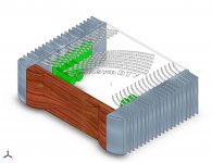
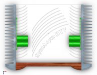
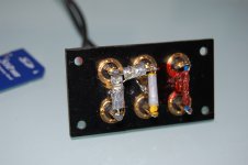
The first 2 pics are my concept, some changes might be made yet.
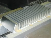
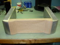
The last 2 are what I have actually completed.
Heatsink is machined from billet, size is 2." x 4.75" x 12". The front panel is is oak. I am not sure of what finishes to use. Maybe polish all aluminum and oil on wood?
Transformers are on the way to me.
I hope to order parts in the next couple weeks. It"s just way to cold in my garage right now to do anything.
jim
The first 2 pics are my concept, some changes might be made yet.
The last 2 are what I have actually completed.
Heatsink is machined from billet, size is 2." x 4.75" x 12". The front panel is is oak. I am not sure of what finishes to use. Maybe polish all aluminum and oil on wood?
Transformers are on the way to me.
I hope to order parts in the next couple weeks. It"s just way to cold in my garage right now to do anything.
jim
Attachments
Hello all, Nice to see folks moving along with this amp. I thought I would share my chassis progress.
The first 2 pics are my concept, some changes might be made yet.
The last 2 are what I have actually completed.
Heatsink is machined from billet, size is 2." x 4.75" x 12". The front panel is is oak. I am not sure of what finishes to use. Maybe polish all aluminum and oil on wood?
I think aluminum has to anodized to better dissipate.
Did you cut metal and wood pieces yourself?


 Show us the final apperance of you amp when you're done. I'm curious, I'm sure it would look beautiful! Are you a machinist?
 Al & Ed, Thanks for the comments.
lgreen, why the $$% heatsink? it seems that you don't like doing this
jim
Yes Jim you are very perceptive! I go carefully and slowly but still break a lot of taps in the hole and then I break the tap removal tools.
Yes Jim you are very perceptive! I go carefully and slowly but still break a lot of taps in the hole and then I break the tap removal tools.
i don't know how much perception that took
")
pm me and maybe together we can make tapping not so frustrating for you.
i don't want to stray too far ot in AAK's thread
jim
Hi All,
Attached is the latest Assembly Instructions document. I cleaned it up a bit adding some additional details where needed. I also added three transistor matching circuit diagrams for matching the input Jfets and output Bjts.
Since I couldn't include the Amplifier Schematic, PS Schematic, and Parts Placement Diagram in the document because of file size constraints I've attached them to this post.
Regards,
Al
Attachments
the PCBs are delivered.
The assembly instructions MUST remind the builders that these two FETs should be assembled the right way around.
The k170 are reputed to be symmetrical, i.e. Drain and Source can be swapped and the device operates identically. If this really is the case then inserting them back to front should make no difference to performance. Can you guarantee that?
Hi Stanley,
Whatever you do the amp should be dead quiet (no AC hum) with the inputs shorted to ground. In my set up it's dead quiet with the inputs floating.
Regards,
Al
Hi Al,
My amp is also dead quiet without the RCA cables(input floating). The input FETs are quite sensitive and they will pick up hums if I use less-than-perfect RCA cables.
I had to make some modifications (shielding the mix resistors) to my $2 stereo-to-mono converter so that it does not pick up hums.
I have done only basic matching of the SST pairs & JFETs, offsets on both channels are less than 2mV.
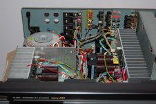
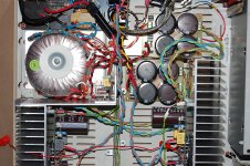
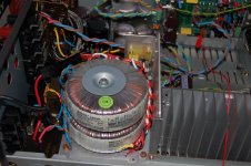
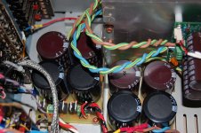
I have installed the SymAsym PCBs inside a recycled AV amp case. The case is reasonably roomy - 6"(H) x 16"(D) x 17"(W) and I used the original heatsinks & the binding posts for outputs.
I made two external power supply boards, each with 4x 8200uF and 8x MUR1520 diodes. I did not leave enough space between the MUR1520s and they can get hot (80C) under extreme loads (200W into 4 ohms).
I installed extra aluminum plates to the small heatsink & they also serves as extra shielding for the transformers.
I am listening to the SymAsym and it sounds good & detailed.
Thanks for good works.
Cheers, Stanley
Attachments
- Status
- This old topic is closed. If you want to reopen this topic, contact a moderator using the "Report Post" button.
- Home
- Amplifiers
- Solid State
- SymAsym - "The Sequel", AAK's PCB Builders Thread