If you are going to tap off a little bit of positive feedback to the input then the R will go to the NFB side and the C will go to the signal ground side. i.e. bootstrapping the input impedance.Pingrs said:“..it does not matter whether 499R is before or after the parallel 470u/100n. That is only difference I can see”
I’m sure I read a post that suggests a preference for the C to terminate to ground, rather than R. Can’t remember why, though.
Brian.
Other wise there should be no measurable difference to the order of these two components and I doubt I could hear an audible difference.
hi.
I've read that in this model the suggested drivers are 2SA1837/2SC4793 i have stability problem with them.
at bias set under 13-14mv across one emitter resistor amplifier makes white noise oscillates, and bias itself destabilizes on - side is normal 10mv but on + goes up 40mv and when i touch radiator drops to normal 10mv but even then amplifier make noise.
when bias is set more then 14mv everything is stable no oscillations but when i turn it off and on there is whistle noise, hum for 1-2sec.
I use design 5.3 but the PCB is little changed so a can fit longer silver mica caps. just more space.
with on-semi MJE15031/MJE15030 as drivers everything is stable from 0 to 40mv as bias, no turn on noise.
what I should change to make them stable as they sound much nicer then MJE more colorized interesting
sorry for my english if theres any mistakes.
I anticipate any help.
It's been a long time but I have finally finished my 5.3s. I tested them first by feeding a signal from a sig. gen and comparing input and output voltages on a scope. Everything seemed fine. Today I connected them up to my hifi and they are performing really great.
A big thanks to all invoved in their design and development. A big thanks to Ryssen too for organising the GB. I'm glad that I bought another two pcbs - I may go with active crossovers. I'm also thinking of bridging.
Has anyone else bridged these amps?
A big thanks to all invoved in their design and development. A big thanks to Ryssen too for organising the GB. I'm glad that I bought another two pcbs - I may go with active crossovers. I'm also thinking of bridging.
Has anyone else bridged these amps?
chalkandtalk said:Does anyone have any of these boards that they are not going to use?
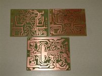
If you mean the AAK version, then no, but I did etch a Symasym pcb based on MikeB's original layout, one only, top LH one in picture (the other two are also Symasym)
If it's of any use, you're welcome to it.
Regards,
Brian.
Attachments
AAK said:Hi JimS
Thanks for suggestions. I moved the input terminals so now you can
use Phoenix type terminals for the transformer inputs, and added vias to both sides of the Wima input cap to accommodate a larger cap.
I also added a couple leds after the fuse that serves as a blown fuse indicator, and holes to mount U3,U4,U5,U6 to the main heatsink. I tried to figure a way to fit a hole on the board for mounting the BD139 to the main heatsink but it's way to tight. So for the BJT version the BD139 still needs to be mounted to one of the output transistors.
Here's my latest board with all the changes mentioned above. This is my mosfet version of SymAsym. The BJT version is basically the same accept I have to swap to pins on each output transistor.
Best Regards,
Al
Hi AI,
Can I make (etch) some PCBs for myself from your last version or I'll need gerber, bom files?
Is it compatible with 35V supply rails?
Thanks and regards.
Sorry AndriyOL, the new PCB that you refered to from back in 2007 has not been tested yet. I've been really busy with my new job since then. Boy, I wish I still had my old state job, but oh well.
The good news is that I've been recently getting that itch again, and with things cooling down at work somewhat, I'm seriously thinking about getting back into it. If I do in the near future I'll keep you posted on how the testing is going.
Best Regards,
Al
The good news is that I've been recently getting that itch again, and with things cooling down at work somewhat, I'm seriously thinking about getting back into it. If I do in the near future I'll keep you posted on how the testing is going.
Best Regards,
Al
I'm back!
Ok, I'm a few years late to this amp. But that doesn't mean I cannot pester you all with my bad questions.
I just built a DX and Carlos had his turn, and now its yours.
Firstly- I have skimmed this thread and read the first 100 pages (its currently 280+ if you save as a pdf).
I see that this is designed for plus and minus 50 VDC. Yet from my reading most people have built using less.
So my questions is why +/- 50? Someone said that 50 is the "max" but isn't 50 the "ideal"?
I am ording my transformer so I need to know what the best values for the DC supply are.
Hi L,
there's the limitation of 1pair in the output stage.
The device is a plastic package and that combined with maxPd~130W to 230W limits what can be driven from whatever voltage.
A 130W 150degC device will not drive a reactive 4ohm load from +-50Vdc.
It should be able to drive a moderate reactance 8ohm speaker, but I would expect it to show some weakness trying to drive a severe reactance 8ohm speaker.
Lowering the supply rails to ~+-40Vdc will allow any 8ohm speaker to be driven and maybe even a moderate 4ohm speaker.
Re: Quiescent current
The quiescent current for MikeB's V5.3 SymAsym should be 55mA. This represents 12mV across one of the output emitter resistors. Across two resistors, this is 24mV.
Regards,
Steve
SmellOfPoo said:What is the proper quiescent current setting? Searched the whole thread, but I´m not shure about what I found.
Measuring across both emitter resistors I set it to 12 mV, is that o.k.?
The quiescent current for MikeB's V5.3 SymAsym should be 55mA. This represents 12mV across one of the output emitter resistors. Across two resistors, this is 24mV.
Regards,
Steve
")
Hi Steve,
Your bias will depend on how well the parts are matched as well as the specific devices you are using. Specifically, you can find this out by running your amp at about 10 ~ 20 KHz into a 4 ohm load at a lowish level. You will see where the distortion reaches a minimum, then starts increasing again. You can try this at various frequencies if you want. Wherever your minimum is, that's what your bias should be set at. Note that setting bias too high will always end up with higher distortion.
I was pleasantly surprised when I read Doug Self's book and had my long held findings supported by his work as well. Completely separately verified. That's a good sign.
-Chris
That's not really a correct answer. I used MJW0281A and MJW0302A and ended up with around 20 mA bias I think. I posted the exact value in the original pages. Most manufacturers were running their outputs around 20 ~ 30 mA per device before the "hotter is better" silliness that became a long lasting fad.The quiescent current for MikeB's V5.3 SymAsym should be 55mA.
Your bias will depend on how well the parts are matched as well as the specific devices you are using. Specifically, you can find this out by running your amp at about 10 ~ 20 KHz into a 4 ohm load at a lowish level. You will see where the distortion reaches a minimum, then starts increasing again. You can try this at various frequencies if you want. Wherever your minimum is, that's what your bias should be set at. Note that setting bias too high will always end up with higher distortion.
I was pleasantly surprised when I read Doug Self's book and had my long held findings supported by his work as well. Completely separately verified. That's a good sign.
-Chris
- Status
- This old topic is closed. If you want to reopen this topic, contact a moderator using the "Report Post" button.
- Home
- Amplifiers
- Solid State
- Symasym 5.3 "AAK model" builder's thread