Bias a bit on the high side - 1,26 V between emitters
Took my AAK Symasyms off the shelf after some years. One is working perfectly, the other measures 1.26 V beetween output transistor emitters when trimpot is turned fully counterclockwise. I'm no elctronics engineer, but to me that doesn't seem right.
What is the cure for that disease?
Took my AAK Symasyms off the shelf after some years. One is working perfectly, the other measures 1.26 V
beetween output transistor emitters when trimpot is turned fully counterclockwise. I'm no elctronics engineer, but to me that doesn't seem right.What is the cure for that disease?
What do you mean by lpt, please?
Long Tail Pair - input differential transistors, possibly the first two transistors in the input signal path. Match these for DC offset.
from wiki:
'A differential amplifier is a type of electronic amplifier that amplifies the difference between two voltages but does not amplify the particular voltages'
Maybe remove then match a new pair for the board?
Hi Groundloops,
Go back and check everything to make sure that nothing was put in backwards. Check all the diodes, the thermal feedback transistor BD139, and the bias pot. Also recheck all the solder connections. If you're not blowing fuses most likely that's all it is.
Best regards,
Al
Go back and check everything to make sure that nothing was put in backwards. Check all the diodes, the thermal feedback transistor BD139, and the bias pot. Also recheck all the solder connections. If you're not blowing fuses most likely that's all it is.
Best regards,
Al
Last edited:
50w version
hi, i just want know i want to buy the 150w version and look for further information thanks
hi, i just want know i want to buy the 150w version and look for further information thanks
Welcome! This thread is for all those who bought the PCB for Mike Bittner's Symasym 5.3, this PCB model designed and tested by "AAK", and organized / produced by "Ryssen". AAK's design implements several incremental changes, most notably very linear Toshiba output transistors (and drivers), a change also rcommended by Pavel Macura (PMA), and 50V rails instead of 36V. All this is done in a compact PCB design of 5x3", intended to mount on top of a 4x5" heatsink.
It is for all discussion related to the actual building process: BOM, components, modifications, testing, functionality, and eventually, one might hope, sound quality
Related threads and posts:
PCB group buy , with all PCB related complementary info in the first post of the thread. This round of the GB is closed, but another round may be forthcoming if interest keeps coming in strong.
AAK's design
Mike Bittner's original design
Pavel Macura's review and technical recommendations
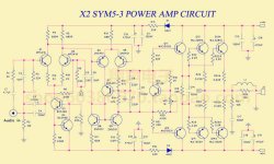
Symasym5_3 rated at 150W under 8 Ohms
This listing is a bare PCB of a high power amplifier, output power 150W( +/-55V)at 8 ohms loading. The design is based on Symasym5_3.
The boards are fabricated with 2.0mm thick fibre glass(FR4) , super thick copper and double sided solder resist coating for best reliability and durability.
Operating status: Class AB (--- ayanhu81 ebay shop welcome you to buy it ---)
Operating voltage: + - 20V ----- + - 45V
Distortion: THD is 0.002% into 1 kilohertz and full power
THD is 0.005% into 10 kilohertz and full power
Input interface: mono signal input
Output Interface: mono speaker output
Power Source: Dual-supply operation
PCB dimension : 138mm x 50mm .
PCB thickness : 2.0mm. (--- ayanhu81 ebay shop welcome you to buy it ---)
Copper thickness : 75um -- FOUR times normal process of copper thickness.Tin plated surface.
Hi Bigcat
,Did you build that kind of SymAsym ? I believe that you could get 150W with 2 Ohm (where there are holes in the response of your 8 Ohm speakers), this with a very good PSU.
Please, did you see that the silkscreen shows written 35V on the boards you refer ? These are mostly the same boards that Jims_audio sells in eBay. Yes they are very well done, and with drivers 2SC4793 and 2SA1837 associated to the Sanken 2SC6145AY and 2SC2223AY they sound very, very good : I did that with the boards I got from Jims_audio. The transformer was the 25Vac-0-25Vac 300VA that is used normally with the SymAsym ...
Best regards
rephil
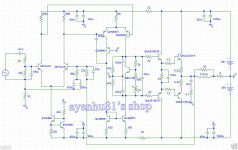
Hi, I've joined both schematics the 100w and the 150W for the 150w they add two more output and the rest seems remain the same diagram.
What do you think about...
Regards
Bigcat
Hi Bigcat
,You should get the full specification of power for a power amp : it is always given as xxxWatt on xOhm. The power supply provide you (doing the maths) with the maximum you can get from 8 (or 4) Ohm speakers : it is normally what could interess you. When you say 150W with the first schematic and 150W with the second schematic, you should understand that it is 100W on 4 Ohm, and the other one could be 150W on 2 Ohm ... It is mostly the same circuit for both ! On 8 Ohm, they will provide the same Watts with the same PSU. No it is not that simple to get more Watts using a higher voltage PSU : they are also some transistors that will burn (MPSA18), and other will become hot ...
Both schematics could give you 60Watt max on 8 Ohm with + and -36V that they use both. The difference with the doubled number of power devices is that it will provide you some advantage in THD if they are well matched. It relaxes also the SOA requirement as a double number of transistors will share the current needed by the load. Don't be fooled by the numbers ! The first schematic is plain the one they have taken from PMA or Michael Bittner our members here, and Michael Bittner
 IS the one that did give to us all, for free, this very nice sounding power amp. The comments you read and report here are those from the chinese sellers. Sellers are always aware that more Watt is more appealing, and it will sell better ...
Please, get some good book and read about power amps (e.g. High-Power Audio Amplifier Construction Manual , Randy Slone (R.I.P), Mc Graw Hill).
Best regards
rephil
Hi bigcat,
Also read books by Doug Self and Bob Cordell. I have them both as do most members interested in solid state amplifiers.
I built these amplifiers and they sound excellent. Performance was higher than I expected. These were a group effort with Mike leading the charge. Understand that there were contributions made by a few other members too. One thing that was discovered was the layout of the PCB had a big effect on distortion. So use the rev 5.3 PCB, or some that were designed later. I also built later versions of the 5.3 by AAK as well.
-Chris
Hi Bigcat
I subscribe me too to what Anatech wrote :
" Also read books by Doug Self and Bob Cordell. I have them both as do most members interested in solid state amplifiers. "
I have also these books that are at a more advanced level as the one from Randy Slone. These are the next step, for the day you will ask yourself "why", and "how to" ...
Have a nice day and thumbs up for your builds !
Best regards
rephil
I subscribe me too to what Anatech wrote :
" Also read books by Doug Self and Bob Cordell. I have them both as do most members interested in solid state amplifiers. "
I have also these books that are at a more advanced level as the one from Randy Slone. These are the next step, for the day you will ask yourself "why", and "how to" ...
Have a nice day and thumbs up for your builds
! Best regards
rephil
Yes you can power two amplifiers from the one centre tapped transformer.
Build one PSU using one bridge rectifier (either 4 power diodes, or an integrated).
Take the three output wires (+, 0, -) to one amplifier. Take a second set of three output wires from the PSU to the second amplifier.
Both these amplifiers will share the SAME Zero Volts. This creates a loop when connected to a source that has a commoned Signal Return.
Attenuate the interference current in that loop by following D.Joffe's HBRR/HBRL solution.
With a 600VA transformer you can supply between 300W and 600W of total maximum power successfully in a domestic listening environment.
Your 39Vac transformer should give supply rails of about +-56Vdc. This should give a maximum output of around 150W into 8ohms.
Inside your total of 300W to 600W.
Theoretically you could power 4ohms speakers, but I am not sure the AAK 2pair output stage would be up to that duty when fed with +-39Vdc supply rails.
Last edited:
AAK_ amp_version
Hi, so the best solution is always One PSU for One amp, I think i stick with your idea, and i can go with 4 ohm for one 600va_39-0-39V with AAK design amp. I regulated the dc output 54-0-54v to 50-0-50V to respect the design.
Thanks for the advice about the ground loop. (PS. i have 2 toroidal transformer 600va 39-0-39v, and my first idea was spare one for another project.)
First I would to present to you, I have technical electronics school degree. Here the little story about audio , I have 10 amps for my home theater is about 2600W, 2x Crown, and 8x 4B Bryston, its a 11.4 channels LCR plus 4 surround side, 4 back surround and 4 subwoofers. I have design all the system and the routing on my own. I need 2 more amp, about 200W for some changes in my home theatre.
So I decides to build the two next ones. Its my first time building amplifier experience and i'm very excited to begin my project.
I appreciated so much your advices, and I'm full confident about the final result.
Best regards,
Bigcat.
- Status
- This old topic is closed. If you want to reopen this topic, contact a moderator using the "Report Post" button.
- Home
- Amplifiers
- Solid State
- Symasym 5.3 "AAK model" builder's thread