David,
I took your hint, and perhaps simplified it a bit...Both your mod and this simplification thereof remove the excessive reverse bias at (modest to severe) clipping as an issue even with the output stage gain restored to near two. However, it does once again allow some cross-conduction when over-driven, which could be damaging.
Perhaps owing to the cross-conduction when over-driven, I'd still vote for either some kind of clipping, or reduced gain in the output stage...
Comments invited...
Dan
Hi Dan,
Yes this is better.
Do you really want to run the bias in class A?
It's at 2.4A right now.
David.
Last edited:
For whatever it's worth, I just subbed MJ21193/4s in a 207A and it runs just fine; yet faster transistors might be problematic, haven't tried those. I believe I'll need substitutes for the old RCA 40409/10 drivers and VAS stage devices. I'm going to replace all resistors with quality film caps and update the boards to the B version, and give them a new listen. They just didn't have the air and power that my Leach amp does, as suggested by the higher order distortion products as power increased from a few watts.
207A is the Tiger .01 as I'm sure you know and quite different from this amp. Good to know that the MJLs work they'd be my first choice as long as they are fast enough:
http://www.diyaudio.com/forums/solid-state/41926-universal-tiger-9.html#post574726
Hi Pete,
That's got to be one of those old RCA TO-5 press fit in a rectangular heat sink with folded fins that the tigers used.
David.
Yes.
RCA 40409/40410 replace with 2N5320/5322
http://www.centralsemi.com/PDFs/products/2n5320-5323.pdf
Electronic Components & Supplies
Electronic Components & Supplies
Also look at:
2N5680/5682
http://www.newark.com/multicomp/2n5680/bipolar-transistor-pnp-120v-to/dp/35C0729
http://www.newark.com/multicomp/2n5682/bipolar-transistor-npn-120v-to/dp/35C0731
Class A?
David,
Good catch...No...I wasn't really planning for class-A...It's just that I didn't re-check the bias current after the mod.
Your catch points out that we still need to do a number of sims to pick "the winner". I'm kind of leaning toward the diode idea because it's kind of elegant, and preserves the gain of 2 in the output stage for the reasons that Pete likes.
Thanks...
Dan
Where we are?
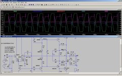
Here's a post of a Tiger amp with some minimal mods...they help a lot with cross conduction, and excess reverse Vbe on the drivers, and honor Pete's gain of two int he output stage request. The clamping diodes are shown a bit differently, but it's actually the same connection as earlier.
I'm sure that there are other ways to tweak, but this seems to simulate ok.
Reality will depend how good the models were.
There is still, if you overdrive heavily, too much reverse Vbe...
So..we could fool some more with other clamping ideas, or put an appropriate limiter in front of the amp...
Attachments
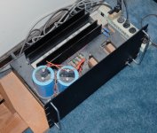
Here's a shot of my dusty and much neglected Tiger. I built it from scratch using only the magazine articles well over 20 years ago. The boards were etched from the published patterns and all the semiconductors are the original part numbers. There's a large hole under the heatsink and the boards are directly under the output devices. The filter caps are 19000uF each and it uses two transformers because I didn't have one with a suitable center tap. The chassis is a 10" high rack panel attached to whatever industrial surplus I could find at the time. Heatsinking is generous, again using whatever extrusion was available from the scrap pile. The amp has been in daily service since it was built and I've only managed to blow it up on the test bench, never in the system. If I built one today (I wouldn't) hopefully it would be more compact and not have bare power terminals! It does live in an inaccessible location.
Attachments
A bit about the sim with MJL parts:
http://www.diyaudio.com/forums/soli...lls-power-amplifier-book-183.html#post2587761
Might be interesting to look at some front ends now that we have some solutions to the output stage issues. I thought the Jensen JE-990 front end, with simplifications might be interesting it is basically a Self design but I like to give credit to Jensen since he did it first.
The fully comp Tigersaurus front end with zener regulation is also interesting for those who like fully comp designs. So many possiblities.
FETs in the diff pair is an interesting option since both Bob Cordell and John Curl favor them. The ultra low input current allows for no input cap and very low input offset voltage.
Might as well mention that I thought it was rather funny that they bragged that the Tiger amps had a response to .5 or 1 MHz IIRC - it went through my mind that yes and then they blow up! The input HF filter should be reduced to a reasonable frequency.
David,
Good catch...No...I wasn't really planning for class-A...It's just that I didn't re-check the bias current after the mod.
Your catch points out that we still need to do a number of sims to pick "the winner". I'm kind of leaning toward the diode idea because it's kind of elegant, and preserves the gain of 2 in the output stage for the reasons that Pete likes.
Thanks...
Dan
Hi Dan,
If the emitters of the drivers could some how be supplied from the rails then the reverse bias of the Vbe would be eliminated or at least minimized. But all my attempts to do so resulted in greater cross conduction. That's when I came up with the idea of the virtual ground. The diodes take the punishment instead of the drivers, Maybe something else along this line.
We haven't even taken into consideration the effects of a reactive load. That could be brutal under a reverse bias condition especially with poorly designed speaker loading.
In the late 90s a very prominent musical instrument company decided they wanted to get into pro audio. They put out a sub enclosure with an 18" driver. The enclosure loading was wrong and the dust caps where being blown off the driver. Can you imagine what the amplifier was seeing. Not that his amp will ever see anything like that, but mistakes do happen.
Worst case conditions can go beyond imagination.
David.
David,
Good catch...No...I wasn't really planning for class-A...It's just that I didn't re-check the bias current after the mod.
Your catch points out that we still need to do a number of sims to pick "the winner". I'm kind of leaning toward the diode idea because it's kind of elegant, and preserves the gain of 2 in the output stage for the reasons that Pete likes.
Thanks...
Dan
Hi Dan,
I do believe I left the bias current to high in my example and that might account for the some of the cross conduction you were seeing.
David.
A Baker clamp protects from going too far into saturation, not for the reverse bias condition.
I tried a simple Baker clamp with a silicon diode and it did not work probably due to the high currents in the drivers and outputs.
You didn't specify if you intended the clamp for the VAS, drivers or outputs.
Here's what was said on the baker clamp idea earlier:
http://www.diyaudio.com/forums/solid-state/41926-universal-tiger-3.html#post2204629
The other thing is that while some fixes may seem to work ok in sim, with a resistive load, the amp also worked pretty nicely into a resistive load, but liked to fry a lot when a speaker was connected AND you merely unplugged the input while it was on, or plugged in the input. Sim that!

I don't have a good answer, btw... on how to "fix it".
Oh the other thing is that once you take the output stage down to a gain of 1, it's kinda a different amp? And wouldn't you want to run a follower output and a different driver stage, etc etc at that point?
_-_-bear
Those issues actually do show up in simulation. Lighter loads allow the outputs to go deeper into saturation where they stick and cross-conduct even more. A speaker with the impedance peaking to 20 or 30 ohms will allow deeper saturation without the diode fix shown in this thread. You wonder why it blows up when you pull out the input plug - I think it is safe to say that the hum or RF picked up clips the output putting far too much reverse Vbe on the drivers, also shown in this thread, destroying them and making the amp go up in smoke. This is my theory and I'm sticking to it until a better one surfaces.
The cross conduction is, for a 20 KHz signal a fairly low percentage of the period, but as you go up in frequency the rep rate of the cross conduction goes up and it become a much larger percentage of the period which would lead to destruction of the outputs. RF is a very bad thing for this amp.
On top of it, we are finding oscillations due to the global feedback loop. I think that these are device dependent however it seems to do it with more devices than not. I thought I found a set of devices that worked way back years ago when I simulated it and checked the loop gain. We will have to revisit this and check the real hardware.
Last edited:
Hi Pete,
Will you be doing a sim of the Tigersaurus as well. I'd be interested to see how that fares.
David.
Decided to do it, it looks more refined with emitter degeneration, zener regulated front end, and more complex compensation:
http://www.diyaudio.com/forums/solid-state/189970-swtpc-tigersaurus-250w-amp-simulation.html
Don't think the diode clamp will work with the regulated front end without some changes.
http://www.berners.ch/McIntosh/Downloads/MC2125_ser.zip
See 4C and 16B.
Ignoring the outputs, the cfp driver stage has a gain of about 10. They were very stable, sounded good, and didn't blow up. The MC502, 2120, 2125, 2200, 2205 used the same ±V, the same driver boards, just more (or less) outputs and drove a different impedance.
See 4C and 16B.
Ignoring the outputs, the cfp driver stage has a gain of about 10. They were very stable, sounded good, and didn't blow up. The MC502, 2120, 2125, 2200, 2205 used the same ±V, the same driver boards, just more (or less) outputs and drove a different impedance.
Hi Pete,
The diode fix seems to fail on Q5 when the input is set to 5V.
The reverse bias of Q5 Vbe is a bit over -12V.
David.
I thought I had previously tried it with 4 ohm loads but now when I run it I notice that it also fails with low impedances, and does virtually nothing with a shorted or very low Z load.
Years ago, I notice that the independent feedback circuits for the pos and neg halves of the outputs could be combined by simply connecting the driver emitters together and I wondered why they didn't do it that way. This solves the reverse Vbe issue since each junction protects the other from reverse Vbe. I believe that they used two feedback sections in order to provide more stable bias in the drivers and a compromise for an already built UT might be to put a 10 ohm resistor from emitter to emitter and then rebias it of course. Also check for bias stability, another area that probably needs attention.
This is similar to the 2 10 ohm resistor arrangement that you showed.
Last edited:
I thought I had previously tried it with 4 ohm loads but now when I run it I notice that it also fails with low impedances, and does virtually nothing with a shorted or very low Z load.
Years ago, I notice that the independent feedback circuits for the pos and neg halves of the outputs could be combined by simply connecting the driver emitters together and I wondered why they didn't do it that way. This solves the reverse Vbe issue since each junction protects the other from reverse Vbe. I believe that they used two feedback sections in order to provide more stable bias in the drivers and a compromise for an already built UT might be to put a 10 ohm resistor from emitter to emitter and then rebias it of course. Also check for bias stability, another area that probably needs attention.
This is similar to the 2 10 ohm resistor arrangement that you showed.
Hi Pete,
I'm not sure if this is what you had in mind.
This solves the problem with the reverse bias but does nothing for cross conduction in the outputs.
The circuit I proposed resolves both but limits the current to the drivers and thus the output transistors. It works fine for this sim, but if you were to use larger outputs that require more drive current the resistor values in the diode-resistor string would have to be so low that 10W components would be required.
We wouldn't want our colleagues to laugh at us.
How can we make this more efficient?
David.
Attachments
bias stability...
David,
The 10 ohm resistor between the emitters will cause bias (quiescent) current stability issues. Now the gain to the difference of the voltages in the Vbes and the bias setting diodes is about 10, where it has been about 1. I think that will make the bias difficult to set with any stability over temperature.
Dan
- Status
- This old topic is closed. If you want to reopen this topic, contact a moderator using the "Report Post" button.
- Home
- Amplifiers
- Solid State
- Swtpc Universal Tiger Improved And Simulation