Thanks David for confirming this!
Hmmm, yes those oscillations are not good, perhaps another issue but I have subsituted all the devices so it is hard to say for sure. The oscillation bursts come at the zero crossings and the outputs do turn off completely once the other turns on, so it might be due to low Ic beta and Ft droop in the outputs. I don't fully trust the sim with the higher speed outputs in place, perhaps base stoppers would help. Let me see if the MJL sim does it also.
Hmmm, yes those oscillations are not good, perhaps another issue but I have subsituted all the devices so it is hard to say for sure. The oscillation bursts come at the zero crossings and the outputs do turn off completely once the other turns on, so it might be due to low Ic beta and Ft droop in the outputs. I don't fully trust the sim with the higher speed outputs in place, perhaps base stoppers would help. Let me see if the MJL sim does it also.
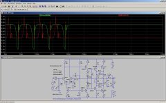
Zoomed in on the oscillation and I measured a period of .10 uS which is about 10 MHz. I don't really trust the sim much at this frequency since all of the device lead and board routing parasitics have not been included. It is interesting that it oscillates anytime the output device current changes abruptly, from off to being driven in the crossover region, and even coming out of sticking.
Just looked at the VAS and it is there also, so does this mean it is a global loop issue?
It seems that if you reduce C3 to 50p and it mostly goes away. There is ringing left
that seems to be the loop trying to correct for clipping and crossover distortion.
Just looked at the VAS and it is there also, so does this mean it is a global loop issue?
It seems that if you reduce C3 to 50p and it mostly goes away. There is ringing left
that seems to be the loop trying to correct for clipping and crossover distortion.
Last edited:
Zoomed in on the oscillation and I measured a period of .10 uS which is about 10 MHz. I don't really trust the sim much at this frequency since all of the device lead and board routing parasitics have not been included. It is interesting that it oscillates anytime the output device current changes abruptly, from off to being driven in the crossover region, and even coming out of sticking.
Just looked at the VAS and it is there also, so does this mean it is a global loop issue?
It seems that if you reduce C3 to 50p and it mostly goes away. There is ringing left
that seems to be the loop trying to correct for clipping and crossover distortion.
Increasing R8 and R10 to .22 does the same.
David.
Interesting, I would not expect that, those resistors are not there in the original design:
http://www.diyaudio.com/forums/solid-state/41926-universal-tiger.html
We should look at the loop gain and then we can make better decisions as to how to fix it, but I don't think I'll spend a lot more time on this since a solution is also needed for the reverse bias issue on the driver B-E junctions.
I think I've had enough Tigers for tonight!
Edit: Just noticed C11 with no series resistor, this will resonate with the output inductor - might be part of the issue and does not look right to me.
Last edited:
Hi Pete,
I ran the sim and yes -18V Vbe of Q5 at clipping. If you plot the base current of Q5 you will see a very nasty oscillation going on as well. Q6 is ~+15 Vbe with base current oscillation as well.
David.
Hi Pete,
For tomorrow then,
This is differential probes of Q5 Vbe (green) and Q6 Vbe (red) with R1 and R16 reduce from 100 ohm to 10 ohm. The voltages have dropped to under 1.8V Vbe.
David.
Attachments
I just looked at the reverse base current in the driver and realized that SPICE does not model this region in that the reverse breakdown voltage is infinite so obviously the current is zero. It would break down in real life with heavy clipping but I'm not sure how much current is required to damage a typical 1-2A Ic driver device.
Out of curiosity, i made some sims and it appears that stability
seems good provided :
1. LTP use 100R resistors for degeneration.
2. A 47 pF compensation cap is added to the VAS.
3. The subsequent nasty pole, created by the use of a 390R
resistor connected in serial with the VAS emitter, is rejected
at an innofensive frequency by bypâssing it using a RC circuit
consisting of a 100nf +10R ..
These very slight mods allow to suppress the lead comp. cap
that goes to the inverting input.
Of course, it can be tweaked further..
Attachments
Last edited:
Nice work David, but consider that as you reduce R1 and R16 to zero it just becomes a standard CFP without gain in the output stage. Perhaps a compromise value that allows 3-5 V reverse Vbe and a bit more gain.
Hi Pete,
Yes I agree a compromise value is needed. I like to make big changes to study the effect and then refine the change based on the new information. I'll try to be more scientific.
David.
Perhaps you might run the sim with a Baker Clamp applied to that device that was showing the excess base voltage (it was base voltage?).
I think this is what the consensus was in another thread on the same amp...
Will look with interest to see the results of the sim... (if i get time I may try it meeself!)
_-_-bear
I think this is what the consensus was in another thread on the same amp...
Will look with interest to see the results of the sim... (if i get time I may try it meeself!)
_-_-bear
Wahab: I haven't found any way to view .emf files in Linux. Could you post the simulation image files as jpg files?
I converted them to gif format..
")
Attachments
Perhaps you might run the sim with a Baker Clamp applied to that device that was showing the excess base voltage (it was base voltage?).
I think this is what the consensus was in another thread on the same amp...
Will look with interest to see the results of the sim... (if i get time I may try it meeself!)
_-_-bear
A Baker clamp protects from going too far into saturation, not for the reverse bias condition.
I tried a simple Baker clamp with a silicon diode and it did not work probably due to the high currents in the drivers and outputs.
You didn't specify if you intended the clamp for the VAS, drivers or outputs.
perhaps someone pointed it out earlier in the thread, but there is significant cross-conduction as the amp comes out of clipping.
Yes, I have pointed this out several times and it is one of several good reasons not to build or use this amp.
Hi Dan it is the .zip file here, and it includes everything you need to run it under LtSpice:
http://www.diyaudio.com/forums/soli...-tiger-improved-simulation-2.html#post2583843
David noticed oscillations in the driver currents, I then also found it in the VAS which indicates a global loop problem. I reduce the 220 pF C3 cap to 50 pF which helps this problem but I've not done a loop gain sim to get a better look at it. You can change the output devices to MJLs or NJLs from Bob's included model file, or get models for the original output from OnSemi and include those if you want to try them. All the models that I've gotten from OnSemi to try in this amp for outputs have had issues, that is why I lean toward Bob's. Andy_C's models are also good, but not so good in clipping where the base current is high. My goal was to get close to the original design and I think Bob's MJL models would work well when/if the PNP device is improved. It seems to sim better with the NJLs for now but they are significantly faster than the originals.
As usual Wahab has completely revamped it with much more modern semis and his twist on how to stabilize the amp. I've not even started to consider how I would best redesign it until I get a handle on all the real world problems - including taking a look in real hardware.
- Status
- This old topic is closed. If you want to reopen this topic, contact a moderator using the "Report Post" button.
- Home
- Amplifiers
- Solid State
- Swtpc Universal Tiger Improved And Simulation