I still have some boards left from the last groupsbuy
Thanks.
Price?
Mono/stereo?
Boards stuffed/empty?
If empty: Estimated parts cost for both channels?
Does stuffed board require only transformer or complete PS?
If transformer only: specs?
If complete PS: Voltage range, minimum wattage?
I prefer SMPS for simplicity and cost savings.
Hi James,
As you know this is a DIY freebie for the forum almost three years back now and Meanman, Patrick, offers these empty pcb for DIYers who are happy to build up the full amp.
If you built the stereo FetZilla, you will pay parts (USD) prices around $300 including two 160VA toroids. There is a comprehensive documentation set at the 'Fetzilla Build Documentation' thread in this Aspen forum at the first post of the first page.
Just here: http://www.diyaudio.com/forums/aksa/207772-fetzilla-build-documentation.html
While the pcb is easy to make, it is not easy; there are a couple of smd semiconductors to fit, but not too small.
The PS is dual; that is, there is a independent rectifier block and filter caps on EACH rail. Thus, you need only to connect the two 160VA 2x25Vac transformer secondaries wires; DC conversion is on the pcb. An smps is fine, but some say that there are considerable differences of sound quality between difference suppliers; the hypex smps is the best but will cost MORE money than the onboard linear supply.
The rails are 36V, and the output is around 50W into 8R. You will get around 75W into 4R. The amp will drive electrostatic speakers very well.
Cheers,
Hugh
Last edited:
Hi,
Can a pair of the fetzilla be wired to a single transformer or SMPS ? Any dumming issue ?
Thanks
No problem
Yes, Syklab, but there is ONE significant issue.
If you use ONE transformer for BOTH channels, you need:
1. Two secondary windings, EACH of two wires, four (4) wires in total
2. ONE secondary, say #1 secondary, must be connected identically on the modules to the positive supply of L channel, and the same wires, paralleled, to the positive supply of the R channel.
3. THE OTHER secondary, say #2 secondary, must be connected identical on the modules to the negative supply of the L channel, and the same wires, paralleled, to the negative positive of the R channel.
If you do this wrong, you will blow up one of the rectifiers on each module, and a pair of the 0.15R power supply resistors under the pcb.
BTW, the single toroid you use for both channel should be rated to 300VA.
The idea of using two 160VA toroids is to build an amp with completely independent power supplies left and right. This is dual monobloc design, and it ensures that there is no channel crosstalk and a slightly improved depth of image.
Cheers,
Hugh
Last edited:
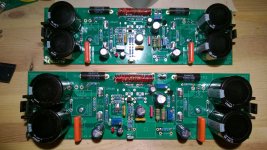
I've finally build two of my four boards aswell. Still waiting on the 1uF M-cap Supreme's I want to use on them, then they are ready to set the bias and be build into an enclosure.
Two questions though:
I was wondering, do I need to either place the caps at C5 and C6 ór place the resistor at PL. or can i leave them both out?
And secondly, I made the induction coil out of 27 windings of 0,8mm wire instead fo the 0,9mm (I couldn't find anny 0,9mm where I live, so subtituted for what i had on hand). I take it this won't pose to be a problem?
A pic of the boards, almost ready to be put in the enclosure.
Attachments
Yes, Eric, this will do it very nicely........ what you are doing with a 100k across the PL pads is introducing nested feedback, and by this you are REDUCING the global feedback. This has advantages for this amp, namely in more resolution, but also, better imaging.
Thanks Patrick!! I appreciate your kind help to me and Eric and your technical skill!
Groetjes,
Hugh
Thanks Patrick!! I appreciate your kind help to me and Eric and your technical skill!
Groetjes,
Hugh
 YesYes soon a new member of the Naksa family
Hi! I have an unpopulated set that I would be willing to let go of. PM me please.Does anyone have a set of boards from the group buy that they want to sell?
I missed the group buy as usual.
Last edited:
- Status
- This old topic is closed. If you want to reopen this topic, contact a moderator using the "Report Post" button.
- Home
- More Vendors...
- AKSA
- Swordfishy/ASPEN FETZILLA power amp