Perhaps the best way to appreciate the value of the switching current sink is to look at the current waveforms in the power supply and load. First up is a reference design that uses a constant current sink made from another linear transistor circuit...
And here is the same supply current going into the switch-mode version of the amplifier...
I think this shows something like 2.8 Amps versus 5.5 Amps from the PSU for the same output power.
And here is the same supply current going into the switch-mode version of the amplifier...
I think this shows something like 2.8 Amps versus 5.5 Amps from the PSU for the same output power.
I ought to explain the above plots a little better: The "Reference" class A circuit I'm using is shown below. To see the supply current share I've split it into two voltage sources and biased the follower to allow the load to return to the mid-rail point. The model I posted earlier for the switching version uses the same basic layout for comparison.
The dark blue plot is the load current ~ [ 4A Pk. (4*.707)^2 * 8 = 64W if that's the accepted way to calc. RMS power in the load]. The other plots show averages of 5.5A and 2.8A in the two designs. For the 80V supply shown this is 440W vs. 224W (I hope someone is going to check this because it's beginning to look too good to be true to me).
BTW; All the single ended designs I have come across use a high-value capacitor to return the load to one or other supply rail - nobody ever seems to use a split supply. I guess it's because it would be impossible to adjust the offset into the follower gate such that the source remained within tens of millivolts of the mid-rail voltage under all conditions?
Attachments
Depending the dynamic resistance of the switching follower, an
ideal midpoint for the load might not be exactly in the middle.
Even so...
You should be seeing an anti-complimented sinewave, and not
some other shape. That waveform was something else entirely...
Something here maybe ain't quite holding voltage drop across
that sense resistor to a solid constant?
If its causing more grief than its worth, ditch it.
AndrewT said:there are many split rail single ended power amp designs and implementations.
following post61, I am now a believer, but don't ask me to explain it.
The mantra is simple really: "The unwanted power is recycled by the inductor."

Mumble; I spent a good couple of hours searching but couldn't spot anything single-ended-ZEN-like with a capless output. Something would surely have to servo the DC to keep it in check? And I'm guessing that that would clutter the circuit beyond recognition.
kenpeter said:Depending the dynamic resistance of the switching follower, an
ideal midpoint for the load might not be exactly in the middle.
Even so...
You should be seeing an anti-complimented sinewave, and not
some other shape. That waveform was something else entirely...
Something here maybe ain't quite holding voltage drop across
that sense resistor to a solid constant?
If its causing more grief than its worth, ditch it.
Pity to ditch it without understanding what's happening tho...
")
darkfenriz said:P.S. You can reduce the dissipation further by supplying the output mosfet follower from a tracking step-down-regulator diven by input signal. That would become some incredible ultra-efficient single-ended class A design!!!
Yes! Use a class-D amp with DC offset to provide the pos supply!
Edit: I now read that you guys already crossed that bridge. Apologies...
jd
QED047,
This circuit is very interesting. I wonder why we have never seen anything like it before. I looked at the circuit of post 59 and have a few comments / questions.
I had to add UIC to the transient analysis command, otherwise it gets hung up running a pseudo transient thing. How did you get it to run?
LTspice can plot power, and you can also have LTspice give you the average value of power. See the "trace data selection" section of the LTspice help file on how to do this. Note that you must have an integer number of 400 Hz cycles for the average power to be correct. There is a start up transient so I saved data from .5 msec to 3 msec.
I realize the current regulator circuit is just intended to demonstrate the principle, but in practice I would consider using some kind of PWM controller. What you have now is sort of a hysteresis regulator that depends on propagation time through the loop. Please don't take this as criticism, because I think this idea is quite innovative.
Rick
A pause for thought: Simplicity is one of the key attractions of the follower & current sink; Dead easy to build, directness of signal path from input to output and so on. Class D on the other hand, takes the input signal and transforms it wholly into an intermediate switching waveform before being re-constructed to resemble the input once again. This step relies heavily on being able to filter the output signal without mangling it in the process. Experts only really need apply.
But the downside of the simple follower is having to have a big (expensive) PSU and even bigger heatsink to dump all the unused power you had to pay for.
Now, with the addition of a few DIY friendly parts, I've found that half the dreaded Class-A power dissipation can be eliminated at a stroke - and the solution is a sort of "black box" that looks every bit like a constant current sink constructed out of any other (i.e. linear) parts.
As for the unwanted voltage component of "the power we don't need", another switching unit could of course be used. In fact a simple buck regulator topology could be used with a conventional transformer/rectifier/reservoir (to avoid the complexity of a full off-line design) but I'm not sure just yet how everything would track together. It could be just as DIY friendly though - and be another "black box" component outside the signal path for nearly all practical purposes.
sawreyrw said:QED047,
This circuit is very interesting. I wonder why we have never seen anything like it before.
Well, I'd really love to be able to take some small credit for raising it - but I bet it's been rattling around somewhere else before.
UIC? I'll look that up right away! I just hit Escape and it ploughed on regardless.I looked at the circuit of post 59 and have a few comments / questions.
I had to add UIC to the transient analysis command, otherwise it gets hung up running a pseudo transient thing. How did you get it to run?
Many thanks for the tips! I've only just started out on the learning curve. BTW there's a *very* obscure reason why I used 400Hz as an arbitrary test frequency. I wonder if anyone knows why (giggles).LTspice can plot power, and you can also have LTspice give you the average value of power. See the "trace data selection" section of the LTspice help file on how to do this. Note that you must have an integer number of 400 Hz cycles for the average power to be correct. There is a start up transient so I saved data from .5 msec to 3 msec.
I realize the current regulator circuit is just intended to demonstrate the principle, but in practice I would consider using some kind of PWM controller. What you have now is sort of a hysteresis regulator that depends on propagation time through the loop. Please don't take this as criticism, because I think this idea is quite innovative.
Rick
I kind of like the hysteretic approach - it means the ripple is managed rather than the switch rate. The latter isn't all that important if the former is well-behaved. The inductor can be pretty big as well. TBH I've been listening to this design with the switch rate dropping into the audio band and heard nothing other than very clear and loud music!
I'm always thrown by magnetics though (inductors strike me as being the least intuitive and the most complex in parameter space of all electronic components!) I'm not all that confident about my choice of parts here - so if anyone has anything to chip-in with...
janneman said:
Yes! Use a class-D amp with DC offset to provide the pos supply!
Edit: I now read that you guys already crossed that bridge. Apologies...
It looks like a switched pulse version of my linear Tower.
I like it!
A switched voltage regulator (bootstrap) on top, and a switched voltage to current converter on bottom.
QED047 said:Something would surely have to servo the DC to keep it in check? And I'm guessing that that would clutter the circuit beyond recognition.
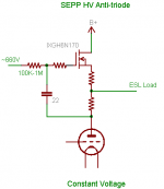
Nah, just search the tube forum for MJK's variant of the Anti-triode.
Its based upon Waveborn's gyrator load, but an active helper too.
Got incredibly useful self-servo action at DC...
Very few changes to implement... Here's a copy of his diagram:
I believe this one would tend to center out around 658V...
The IGBT in this diagram is doin what your switcher ought to.
To be clear, its drawn upside down to the way yours works...
The plate of his triode would be your MOSFET's source.
Attachments
kenpeter said:
To be clear, its drawn upside down to the way yours works...
The plate of his triode would be your MOSFET's source.
 658V? Sorry to be so dumb, but I don't know where to begin trying to analyse this configuration. Can you describe the principle involved?
Thinking on a bit, the problem with the power plots for the abused centre-tap in post#60 may be to do with the way I return the flyback voltage. The recycled energy is a bit toxic when it makes its way out the diode's cathode. Returning it to the PSU and modelling it properly is a bit of a challenge. I'm not seeing anything like it on my breadboard.
Perhaps I should be re-introducing the recycled power into the supply resevoir via an inductor? The flyback voltage goes as high (or low) as you let it, so a capacitor is still needed on the cathode. But it would seem to be a good idea to use an LC combo to pour the volts in gently?
Perhaps I should be re-introducing the recycled power into the supply resevoir via an inductor? The flyback voltage goes as high (or low) as you let it, so a capacitor is still needed on the cathode. But it would seem to be a good idea to use an LC combo to pour the volts in gently?
Not real abuse! It was just Ken's colourful way of promoting the idea of splitting the current sense into two parts with the load in the middle. And yes, inductance alone will not do. I was thinking of some kind of safe "holding tank" to return the flyback e.g. capacitor(s) and couple that inductively to the main supply. Should work in theory - the DC will be the same at each end of the coupling inductor.sawreyrw said:The power in each sense resistor is 1.25 watts, so a 3 watt resistor will not be abused at all. I'm not sure what you mean by 'recycled power', but the cathode of the diode must be connected to a very low inductance point. Otherwise you will have a huge L di/dt spike.
SQLGuy said:400Hz because you want to use this to control aircraft flight control servos? That sounds a bit too obscure, but 400Hz is standard for use on aircraft.
True, but this has a more musical (and whimsical) association. You have to know the right Melody.

Well, 440Hz is a concert A, that used to be standard for orchestral tuning. However, a conductor on another forum mentioned that pitch has been rising for the past few years (i.e. most orchestras tune sharp compared to what was done back in Gershwin's days). I would guess 400Hz to be a G or so, but...?
Eva said:Hi QED047. You are going the right way. In fact, a self oscillating class D amplifier is not that different from your approach, it just uses a voltage comparator and a four quadrant switcing mode current source (one MOSFET to each rail). I only like triangle wave modulators for SMPS, not for audio.
Right on! The most "trust" I have is for the simple follower. This is why I shy away from typical Class D. This trust is both in my own engineering competence and in the even more subjective area of listening.
Eva said:btw: Some of them actually do class A followers because they can't understand anything more complex
I'm not really all that far from that group. However, silly as it may be, so long as the signal path still has a clear line of sight to the load, I don't mind augmenting it with non-linear techniques if they can be used effectively.
Steven said:Ronan van der Zee showed a similar idea in his thesis, see chapter 6.6.3 (page 96). You can download the complete thesis here: http://doc.utwente.nl/14149/1/t000000d.pdf
or check this: http://purl.org/utwente/14149.
Steven
Many thanks for the link. I've been looking at the parallel amp with interest. I've re-modelled my reference Class A (follower and linear current sink) along these lines. For anyone unfamiliar with the parallel amp, in one implementation, a conventional output stage capable of sinking and sourcing current is tied to the load via a current sense. This sense point is used to try to keep the current at a minimum by operating a half-bridge on the other side. The two transistor switches in the bridge source or sink current via an inductor at a variable switch rate. These take over the "heavy lifting" duties and the linear amp serves only as a reference signal.
The motive in Ronan van der Zee's thesis was to improve the efficiency of a typical (already quite efficient) class AB amp. The use of a single ended reference appeals to me (as always because of its simplicity) and as I'm not after extreme efficiency, a few tens of watts here are no problem at all. All in all this is a very interesting idea.
Attached is a schematic of an LTspice sim plus some output.
Attachments
- Status
- This old topic is closed. If you want to reopen this topic, contact a moderator using the "Report Post" button.
- Home
- Amplifiers
- Solid State
- Switching current source for Class A?