QED047 said:
Not sure what you mean here (but it sounds intriguing)... equal impedance to what?
To your class A mosfet reference device, actively anti-copied.
Almost a gimme, with your existing Class D topology, take it!
Free doubling of output power/ halving of output impedance,
whichever way you wanna look at it...
Abuse the sense resistor Luke! Connect the load dead center.
Stand back, and be amazed... Single ended push pull magic!!!
Indistinguishable to both the load and reference device from
single ended parallel. The virtual helper device created in the
bridge is an anti-compliment. Like a slap in the face, you can
call it an insultramentary push/pull behavior.
Search Nelson Pass forum for his Aleph active current source.
Or visit the tube threads and research the Evil Anti-Triode.
Same exact thing, only completely different....
Voltage span across your sense resistor is held constant, thus
currents changes in either half are forced equal and opposite.
Plus your quiescent. Always summing to some quiescent unity...
Hard to see the first time, but quite simple in practice.
Aside from splitting the sense resistor in two equal halves,
you have everything you could possibly need already in place.
QED047 said:This is the point I think you may be missing:
....
I think you may be unused to considering power "stored" in a magnetic field.
Yes it is new stuff to me, but I am starting to get the idea.
Thanks for explaining it detailled, I will study the topic some more later on.
It is a super interesting technology.
Please keep us posted (also with pictures) of your projects evolvements.
....I am still at this point, so sorry for my 'dump' questionsI remember scratching my head a bit when I first met switching topologies
darkfenriz said:Hi QED047
Sorry if you find me pestering, but I have a question, that came to mind:
How does it behave at negative side overdrive?
To my understanding the switching frequency should go down with output voltage because of less steep current ramp. Isn't there a point at which the switching frequency falls into audio range?
Naturally as the output approaches the rails the switching frequency does indeed fall. However, if it ever goes to DC, current control has been lost and the o/p is at the supply rails! I'm not all that concerned about behaviour at clippling. Switching ripple in the audio band would be the least of the sonic problems in these circumstances!
Omicron said:
Wouldn't it be much easier in this design to vary the bias current instead of the supply voltage? I mean you could simply let it track the setting of the volume potentiometer. That way you would have reduced power dissipation at lower listening levels. All the machinery needed seems to be in place already...
Smacks forehead ~ this *has* to be the way to go ~ of course you're right! I've only just begun to play around with the effects of modulating bias current on demand and it is becoming apparent how much more sense it makes to do this and leave the voltage alone.
Off to experiment with centre-tapped current sense now - back later to ask & answer more Q's.
Bigun said:
Great! Thanks for the link. However, I think a practical Signal tracker for bias current would present some challenges in the kind of feedback-free environment I'm trying to create. This is because the modulation of bias current appears to result in a small voltage change at the output of the follower transistor - presumably due to transconductance. In this case I think the rate of change of bias would have to be well below the audible frequency threshold - although a half-second delay shouldn't be too noticable so long as there is no video accompanying the sound! I can half-imagine some kind of peak-envelope with a half-second time constant representing the signal to come.
At the very least it would be great to automatically have the bias reduced to a tiny "standby" amount in the absence of signal, just to save on the eltricity bill. This would help meet my "daily driver" requirements as I tend to leave all my gear running throughout the day while I flit in and out of the room.
In terms of circuit design, it could be fun to implement an "old school" digital circuit with shift registers counters and SRAM spanning a pair of DACs fed from a S/PDIF decoder. Time to dig out my CS8414 chips perhaps
Now I'm hoping kenpeter is still listening in because I'm having a terrible time getting my head around what the "Evil Twin" concept can do for me here...
This seems like an incredibly good deal but it also sounds like you're talking about adding another bunch of stuff on the other side of the speaker? Blindly following your suggestion of just centre-tapping the load mid-way into the sense resistor, I can measure almost half the output impedance as promised but I can't see how wer'e going to double the output power (not without doubling the output swing). The waveform into the load is the same as before.
I'm obviosuly missing something vital here. As it is, the load is AC coupled - surely an absolute necessity with a single-ended output stage where the mid-rail point is rather arbitrarily defined? To double the output power from my circuit the output stage would surely need to be replicated as an H bridge in some way?
EDIT: I think on reflection you are simply reiterating the primary accomplishment of the switching current source in so much as it doubles the efficiency.
Unfortunately searching for the exact phrase "Single ended parallel" doesn't find me a simple picture explaining any particular topology. Can you help here? The keyword "parallel" throws up a load of references to paralleling output devices to increase drive capability.
I have done so, but came back frustrated that I still couldn't understand what's going on. I always glaze over when trying to understand patent-speak and I don't have any experience with tube circuits (despite knowing that they share many of the same characteristics of fets, the differences are enough to distract my simple mind)
It sure sounds simple in practice, which is why before long I gave up trying to model it in my head and simply plugged in two sense resistors and moved the loudspeaker connection to the mid-point. The only difference I can tell is that the o/p impedance has dropped from a measured 0.45 Ohm to 0.25 Ohm. As grateful for that as I am, this is the only thing I can actually see and you sound to be offering so much more!
kenpeter said:
To your class A mosfet reference device, actively anti-copied.
Almost a gimme, with your existing Class D topology, take it!
Free doubling of output power/ halving of output impedance,
whichever way you wanna look at it...
This seems like an incredibly good deal but it also sounds like you're talking about adding another bunch of stuff on the other side of the speaker? Blindly following your suggestion of just centre-tapping the load mid-way into the sense resistor, I can measure almost half the output impedance as promised but I can't see how wer'e going to double the output power (not without doubling the output swing). The waveform into the load is the same as before.
Abuse the sense resistor Luke! Connect the load dead center.
Stand back, and be amazed... Single ended push pull magic!!!
I'm obviosuly missing something vital here. As it is, the load is AC coupled - surely an absolute necessity with a single-ended output stage where the mid-rail point is rather arbitrarily defined? To double the output power from my circuit the output stage would surely need to be replicated as an H bridge in some way?
EDIT: I think on reflection you are simply reiterating the primary accomplishment of the switching current source in so much as it doubles the efficiency.
Indistinguishable to both the load and reference device from
single ended parallel. The virtual helper device created in the
bridge is an anti-compliment. Like a slap in the face, you can
call it an insultramentary push/pull behavior.
Unfortunately searching for the exact phrase "Single ended parallel" doesn't find me a simple picture explaining any particular topology. Can you help here? The keyword "parallel" throws up a load of references to paralleling output devices to increase drive capability.
Search Nelson Pass forum for his Aleph active current source.
Or visit the tube threads and research the Evil Anti-Triode.
Same exact thing, only completely different....
I have done so, but came back frustrated that I still couldn't understand what's going on. I always glaze over when trying to understand patent-speak and I don't have any experience with tube circuits (despite knowing that they share many of the same characteristics of fets, the differences are enough to distract my simple mind)
Voltage span across your sense resistor is held constant, thus
currents changes in either half are forced equal and opposite.
Plus your quiescent. Always summing to some quiescent unity...
Hard to see the first time, but quite simple in practice.
Aside from splitting the sense resistor in two equal halves,
you have everything you could possibly need already in place.
It sure sounds simple in practice, which is why before long I gave up trying to model it in my head and simply plugged in two sense resistors and moved the loudspeaker connection to the mid-point. The only difference I can tell is that the o/p impedance has dropped from a measured 0.45 Ohm to 0.25 Ohm. As grateful for that as I am, this is the only thing I can actually see and you sound to be offering so much more!
QED047,
This is great idea.
Have you considered to put your LC filter before the node: L in
series with the sensing R, (2) Cap(s) to V-, before the L (and
after - for higher attenuation). This will help to reduce switching
noise interference with the output transistor bias.
Thanks for sharing.
This is great idea.
Have you considered to put your LC filter before the node: L in
series with the sensing R, (2) Cap(s) to V-, before the L (and
after - for higher attenuation). This will help to reduce switching
noise interference with the output transistor bias.
Thanks for sharing.
Nope, thats basically all it is... Half the output impedance.
You have measured it correctly.
You could then connect half the load impedance and have
the doubling of output power. With no greater stress upon
the reference device than the original unmodified circuit....
No greater quiescent current, nor current swing in the
reference device. Added current swing comes now from
the active load..
-----------------------------------
A complimentary active load would tend to cancel out 2nd
order distortions, and replace them with higher odd orders...
An insultramentary SEPP active load doesn't cancel anything!!!
Merely copies, and appears a duplicate SE device in parallel.
Neither the driven load, nor the reference device being copied,
feel any hint of a complimentary pull device that would modify
the behavior of the reference (other than seeing the load as-
if twice the impedance, or as-if a matching helper in parallel)...
Single ended distortion profiles are maintained.
-----------------------------------
Aleph is a little harder topology to wrap ones head around
than Antitriode (splitting the sense resistor)... The sensing
bridge is done differently, but the result is exactly the same.
One thing you could steal from Aleph, is abusing an emitter
drop as the reference voltage, and span your sense resistor(s)
across the 0.66V Base to Emitter junction. You then take a
detected error current directly from the collector, to your PWM.
Omicron said:Wouldn't it be much easier in this design to vary the bias current instead of the supply voltage? I mean you could simply let it track the setting of the volume potentiometer. That way you would have reduced power dissipation at lower listening levels. All the machinery needed seems to be in place already...
A cool idea.
Sheldon
StevenOH said:QED047,
This is great idea.
Have you considered to put your LC filter before the node: L in
series with the sensing R, (2) Cap(s) to V-, before the L (and
after - for higher attenuation). This will help to reduce switching
noise interference with the output transistor bias.
Thanks for sharing.
Thanks! I'll bear your suggestion in mind for when I get round to tidying up - although Ken's split-sense resistor tap seems to be a definite inclusion so it may not be quite that easy.
kenpeter said:Nope, thats basically all it is... Half the output impedance.
You have measured it correctly.
Good, that confirms my later suspicions - and my ears are confirming the retention of single-ended sound. If only I could get decent results from my TDS 3014 FFT
Aleph is a little harder topology to wrap ones head around
than Antitriode (splitting the sense resistor)... The sensing
bridge is done differently, but the result is exactly the same.
One thing you could steal from Aleph, is abusing an emitter
drop as the reference voltage, and span your sense resistor(s)
across the 0.66V Base to Emitter junction. You then take a
detected error current directly from the collector, to your PWM.
I suppose I shouldn't be so picky about using a switch-mode IC like that. Having just started using LTspice (literally today) it makes a quite a lot of sense. I'm more of a embedded control and digital design type - in getting interested in audio lately means I've probably drawn some fairly arbitrary divides. (Look who's talking here ~ it wasn't long before I started making a"digital" ZEN)
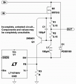
kenpeter said:Here's a very crude picture, sorta what I was thinking....
This PWM is only 100Khz, all my passives are probably dead wrong too.
So are you going to sim it? The results would be very pertinent to the scheme were discussing. It'll be a while before I'm up to speed with LTspice - I haven't even managed to sim a simple common-source amp yet.
Just to show that I'm paying attention, the picture in post#49 shows a buck regulator IC. These have a series switch to the +ve supply which is no good here. A boost reg. with switch to ground is what we need. Unfortunately I can't get LTspice to simulate a LT1170HV in its place. Still getting to grips with the program though.kenpeter said:Here's a very crude picture, sorta what I was thinking....

I believe my disclaimer stated that any and all components
might be completely unsuitable... Glad to hear I didn't waste
my time writing that bit.
Of course, you could maybe use buck to drive an external
MOSFET??? But with the right regulator, no external switch
should be necessary...
I wonder if there is any value in a synchronous rectifier in
parallel with the Schottky? So many watts burned in class
A side already, hardly a drop in the bucket...
Anyways, I just grabbed that power supply regulator as a
convenient black box to simplify my explanation of emitter
comparator Anti-Triode. I figured you probably already had
a superior discrete PWM built, as you quote 500KHz. Didn't
feel any need for that section needed to be re-engineered
by me, certainly not just to show how a simple SEPP bridge
might be implemented...
Now for somebody else, not wanting to PWM from scratch...
TPA2005D1 driving an external mosfet might be suitable???
Might even be able to make use of the differential inputs?
At least the switching framerates are up around 250KHz...
Its hard to find an Audio PWM these days that isn't over
cluttered with "features" that only seem to get in the way.
Especially when you want to do something non-standard
with it, like drive the other half Class A... I think there is
an MSOP8, which has pins and don't need fancy solderin.
I don't know the availability of a SPICE model for that one?
Check TINA-TI to see if maybe its in the default library???
TINA-TI is free like LTSpice, only its TI... I think you have
to use at least one TI part in the schematic somewhere...
http://focus.ti.com/docs/toolsw/folders/print/tina-ti.html
And the specsheet for the PWM mentioned above.
http://focus.ti.com/docs/prod/folders/print/tpa2005d1.html
Hi QED047. You are going the right way. In fact, a self oscillating class D amplifier is not that different from your approach, it just uses a voltage comparator and a four quadrant switcing mode current source (one MOSFET to each rail). I only like triangle wave modulators for SMPS, not for audio.
Don't expect everybody to understand your circuit, then again, most of them wouldn't be so much focused in linear stuff if they understood things better...
Consider the "cascode" switching regulator for the upper supply, it can track the output with less than 0.1% THD (0.01% typ.) and very little phase shift up to 20Khz. No delay is required. This would allow the class A MOSFET to operate at constant Vds with enhanced linearity and "class-D-grade" efficiency.
The regulator should be voltage-mode self oscillating. Like for current mode self-oscillating, there are several operating modes, like phase shift and hysteresis oscillation.
My preferred method is phase shift oscillation: The system will oscillate at the freq. where propagation delay plus LC (or just L plus another pole) phase lag add up to 180 degree, as long as they don't come back to less than 180 at a higher freq. RC lead/lag networks should be used to set self oscillating freq. Oscillation at a freq too close to LC filter resonance (too low) should be avoided or output ripple will be too high...
btw: Some of them actually do class A followers because they can't understand anything more complex This is a nice way to tease them or maybe to tempt them to enter the dark side of electronics muahahaha
Don't expect everybody to understand your circuit, then again, most of them wouldn't be so much focused in linear stuff if they understood things better...
Consider the "cascode" switching regulator for the upper supply, it can track the output with less than 0.1% THD (0.01% typ.) and very little phase shift up to 20Khz. No delay is required. This would allow the class A MOSFET to operate at constant Vds with enhanced linearity and "class-D-grade" efficiency.
The regulator should be voltage-mode self oscillating. Like for current mode self-oscillating, there are several operating modes, like phase shift and hysteresis oscillation.
My preferred method is phase shift oscillation: The system will oscillate at the freq. where propagation delay plus LC (or just L plus another pole) phase lag add up to 180 degree, as long as they don't come back to less than 180 at a higher freq. RC lead/lag networks should be used to set self oscillating freq. Oscillation at a freq too close to LC filter resonance (too low) should be avoided or output ripple will be too high...
btw: Some of them actually do class A followers because they can't understand anything more complex
This is a nice way to tease them or maybe to tempt them to enter the dark side of electronics muahahahaRonan van der Zee showed a similar idea in his thesis, see chapter 6.6.3 (page 96). You can download the complete thesis here: http://doc.utwente.nl/14149/1/t000000d.pdf
or check this: http://purl.org/utwente/14149.
Steven
or check this: http://purl.org/utwente/14149.
Steven
This is a great paper, both the part that analyzes amplifier efficiency with audio signals (which is way below the 70% theoretical maximum for class B), and the part that deals with hybrid approaches.
However, the author seems to ignore the advantages of realizing class D amplifiers as (good old) phase-shift oscillators by taking advantage of the 180 degree phase shift (and the carrier residual) from the output filter rather than fearing it and trying to avoid it. (These advantages are load independent frequency response and very low output impedance).
However, the author seems to ignore the advantages of realizing class D amplifiers as (good old) phase-shift oscillators by taking advantage of the 180 degree phase shift (and the carrier residual) from the output filter rather than fearing it and trying to avoid it. (These advantages are load independent frequency response and very low output impedance).
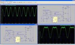
I now have a working simulation (kind of) in LTspice. Files are attached so anyone should be able to play around.
BTW The Transient Analysis phase appears to go on forever, so I always take up the invitation to hit ESC after it gets to around 0.5 I have no idea what this is all about - but it carries on and simulates the model anyway.
BTW The Transient Analysis phase appears to go on forever, so I always take up the invitation to hit ESC after it gets to around 0.5 I have no idea what this is all about - but it carries on and simulates the model anyway.
Attachments
As for abusing the sense resistor as per Ken's suggestion - I still haven't figured out what it really does for us. I have attached a screen-shot of the sim with the load in both positions so anyone can take a quick look at what goes on. The power dissipated in the follower goes way up with the load tied to the center. It doesn't appear to make much difference to the VI product in the load though (actually it makes it slightly asymetric).
Attachments
- Status
- This old topic is closed. If you want to reopen this topic, contact a moderator using the "Report Post" button.
- Home
- Amplifiers
- Solid State
- Switching current source for Class A?