The most obvious solution is to change nothing, and use a voltage doubling rectifier.How would your circuit be used to get 300V DC from 120V AC?
It does have the disadvantage of increased ripple, but must not be dismissed too quickly: tubes perform better at higher voltages.
However, it is possible to make the circuit operate from 160V DC by adapting the turns ratio, the feedback, and squeezing the tube to the limit.
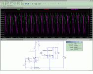
Here is an example, based on the previous circuit (BTW, the sim file I gave earlier is useless, use rather this one).
Incredibly, it is possible to get an higher output voltage, and even more incredibly, the efficiency now exceeds 85%!
But of course, it is not caused by the lower supply voltage, but rather by the changes that were made to accomodate the lower supply.
This shows that the previous circuit certainly has room left for improvement.
Note that the tube is severely stressed, with a high anode current, grid current, etc.
It is not especially healthy, but tubes made for use in the North-American TV sets should have more space to breathe.
I don't know any example of such tubes, but they have to exist.
Attachments
I have measured (in sim, of course, but it looks plausible) a peak anode current of ~0.5A.
I didn't find an abs. max. rating for the peak anode (or cathode) current of EL34, but I suspect it is way excessive.
On the other hand, horizontal deflection tubes designed for transformerless operation on 117VAC mains could probably handle it.
I didn't find an abs. max. rating for the peak anode (or cathode) current of EL34, but I suspect it is way excessive.
On the other hand, horizontal deflection tubes designed for transformerless operation on 117VAC mains could probably handle it.
The tube I used for the physical prototype is in fact equivalent to a PL500 (27GB5), very much like the types you mentionned.Why do you want to use EL34?
Why not use tubes such as PL36, PL504, PL508, PL509.
PL509 gives peaks of 1,4A for short pulses.
But lower voltage pentodes like the EL34 are more suitable, since the peak anode voltage never exceeds ~650V in this circuit, and parameters like transconductance are more important in this case.
And I used the EL34 for the sim, because I couldn't find a reliable spice model for the PL500.
PS:
As I said earlier, deflection tubes designed for low mains voltages probably have an advantage on other types.
The lower transconductance can be adressed by increasing the feedback voltage.
Last edited:
And I used the EL34 for the sim, because I couldn't find a reliable spice model for the PL500.
Have you tried these models: http://www.diyaudio.com/forums/tubes-valves/73466-el504-pl504-spice-model.html ?
They do not model the grid current, which in this case is a fatal flaw, as the oscillator relies on the G-K diode effect for its autobias/AGC.Have you tried these models: http://www.diyaudio.com/forums/tubes-valves/73466-el504-pl504-spice-model.html ?
When I insert the EL504 in the circuit of the EL34 above, this results in an output voltage of almost 500V, which is totally unrealistic: the 27GB5 I used for the physical tests is very similar to the EL/PL504, and I only get 275V output (OK, mine already has a number of hours flight , but a 2 to 1 ratio is really excessive, even for a half worn-out tube).
Incidently, the PL509 looks like a good candidate for this application, it has a very high cathode current.
They do not model the grid current, which in this case is a fatal flaw, as the oscillator relies on the G-K diode effect for its autobias/AGC.
Aha, noted.
I can do some measurements of grid current for those tubes if you want.
Also, what power can be expected from such a SMPS?
It isn't simply a numerical value that is required, but a mathematical expression that the simulator can use to compute the instantaneous value of the grid current as a function of all other tube's voltages and currents.Aha, noted.
I can do some measurements of grid current for those tubes if you want.
The single-ended pentode version provides ~20W of useful power.Also, what power can be expected from such a SMPS?
As I said, there is still room for improvement, and with a tube like the PL509, this could easily be doubled.
A well-designed symetrical converter like the low-power Royer ones above could give a further three-fold increase.
One would have to use an inductive feedback, as the capacitive divider is only a cheap expedient, suitable at low power levels.
I figured you can make the expression by measuring the grid current under different conditionsIt isn't simply a numerical value that is required, but a mathematical expression that the simulator can use to compute the instantaneous value of the grid current as a function of all other tube's voltages and currents.
")
Yeah, that's more or less the way spice models are constructed, but I am no expert in this field, and the result I would arrive at would be pretty crude.I figured you can make the expression by measuring the grid current under different conditions
It is probably simpler and safer to start from a complete, proven model of a similar tube, and tweak the parameters so that it behaves like its glass counterpart.
Yeah, that's more or less the way spice models are constructed, but I am no expert in this field, and the result I would arrive at would be pretty crude.
It is probably simpler and safer to start from a complete, proven model of a similar tube, and tweak the parameters so that it behaves like its glass counterpart.
Well, the model already has got some formula for grid current, but it is commented out.
It seems to me this line was copied from a similar tube.
PS: sorry if i'm going offtopic
I don't know, Robert Mac Lean seems to have constructed his model from data extracted from the datasheet.Well, the model already has got some formula for grid current, but it is commented out.
It seems to me this line was copied from a similar tube.
I have seen other tube models where the G-K diode is modeled like a semiconductor junction, but with different saturation currents, etc.
A well-designed symetrical converter like the low-power Royer ones above could give a further three-fold increase.
One would have to use an inductive feedback, as the capacitive divider is only a cheap expedient, suitable at low power levels.
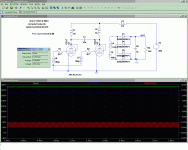
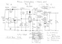
Here is more or less the kind of thing I had in mind.
It's a sim, and the efficiency is only a bit over 70%, which is not bad after all for a tube circuit, but it is certainly possible to do much better, I didn't make an in-depth investigation.
The output power is 100W, and with more powerful tubes, this could be stepped-up easily.
The way the feedback is managed is probably not optimum, but as I said, I am not an expert in vacuum.
A Royer converter requires a feedback waveform with zero crossings well centered on the anode waveforms.
The way I found to do this without applying the straight transformer waveform to the grid was to include grid resistors.
Maybe they are unnecessary, and the grid can tolerate heavy positive voltages without problems, i am not sure, tube experts are invited to comment.
Attachments
Some news:
I tried to build the symetrical converter above, but the only power pentodes I had available were PL500/PL504.
Thus, I simply dropped them as a replacements for the EL34's, without changing anything.
As I haven't found proper models for the PL500's, I couldn't make a preliminary sim test either.
In addition, my HV supply had just failed, and I had to take the risk of an actual live test, directly to the mains.
The oscilloscope was monitoring the secondary voltage
First, things looked normal: the heating took for ever, because it was wired in its real configuration, with the capacitive supply functionning as an almost perfect current source, and then the voltage appeared slowly, and rose, rose, to a staggering 350V! (loaded)
I should have been suspicious, this was too good to be true.
That's when things turned really nasty: there was a loud pop, accompanied by fireworks inside one the PL500.
I think it almost exploded.
At first, I thought the cathode to filament insulation had failed, because I had seen incandescent fragments falling inside the tube.
The autopsy revealed something else: in fact, the anode connection to the top cap had fused, probably caused by a short-circuit between K-G3 and the anode.
The tube then took the full energy of the filter cap through the transformer's winding, which destroyed the connection.
At this stage, I had well understood that the schematic with the EL34's was totally unsuitable for the PL500.
Some people say "semiconductors have ratings, tubes have guidelines", but I can attest this is not always the case....
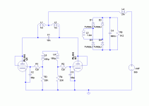
So I adopted a somewhat different feedback configuration, much less harsh on the grid, but without automatic bias, see schematic: the Royer converter requires a drive well centered on the zero-crossings, and in the end I used practically the same technique as for bipolars, using the G-K diode as the B-E in a bjt.
I had learned my lesson too, and I made the first tests at reduced voltage, through a transformer.
As it seemed to work properly, I connected the circuit to the mains in its actual configuration, and it worked perfectly...
Unfortunately, I couldn't make very detailed tests because the heater of one the PL500 failed prematurely, but this time it had nothing to do with a malfunction of the circuit, it was simply old age: most of the tubes I use for my tests are at least 40 years old, and they have many hours functionning behind them.
When I find another tube, I'll be able to resume my tests, but so far, it looks tantalizingly promising.
The 68p/120R on the grids is for stabilization: without them, I had huge VHF oscillations.....
Pics of the prototype will follow soon.
I tried to build the symetrical converter above, but the only power pentodes I had available were PL500/PL504.
Thus, I simply dropped them as a replacements for the EL34's, without changing anything.
As I haven't found proper models for the PL500's, I couldn't make a preliminary sim test either.
In addition, my HV supply had just failed, and I had to take the risk of an actual live test, directly to the mains.
The oscilloscope was monitoring the secondary voltage
First, things looked normal: the heating took for ever, because it was wired in its real configuration, with the capacitive supply functionning as an almost perfect current source, and then the voltage appeared slowly, and rose, rose, to a staggering 350V! (loaded)
I should have been suspicious, this was too good to be true.
That's when things turned really nasty: there was a loud pop, accompanied by fireworks inside one the PL500.
I think it almost exploded.
At first, I thought the cathode to filament insulation had failed, because I had seen incandescent fragments falling inside the tube.
The autopsy revealed something else: in fact, the anode connection to the top cap had fused, probably caused by a short-circuit between K-G3 and the anode.
The tube then took the full energy of the filter cap through the transformer's winding, which destroyed the connection.
At this stage, I had well understood that the schematic with the EL34's was totally unsuitable for the PL500.
Some people say "semiconductors have ratings, tubes have guidelines", but I can attest this is not always the case....
So I adopted a somewhat different feedback configuration, much less harsh on the grid, but without automatic bias, see schematic: the Royer converter requires a drive well centered on the zero-crossings, and in the end I used practically the same technique as for bipolars, using the G-K diode as the B-E in a bjt.
I had learned my lesson too, and I made the first tests at reduced voltage, through a transformer.
As it seemed to work properly, I connected the circuit to the mains in its actual configuration, and it worked perfectly...
Unfortunately, I couldn't make very detailed tests because the heater of one the PL500 failed prematurely, but this time it had nothing to do with a malfunction of the circuit, it was simply old age: most of the tubes I use for my tests are at least 40 years old, and they have many hours functionning behind them.
When I find another tube, I'll be able to resume my tests, but so far, it looks tantalizingly promising.
The 68p/120R on the grids is for stabilization: without them, I had huge VHF oscillations.....
Pics of the prototype will follow soon.
Attachments
When I find another tube, I'll be able to resume my tests, but so far, it looks tantalizingly promising.
I can provide you some PL504 for price of shipment, or if you live nearby, you can pick them up... PM me if interesed
Thanks! I think I'll pick up your offer.I can provide you some PL504 for price of shipment, or if you live nearby, you can pick them up... PM me if interesed
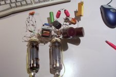
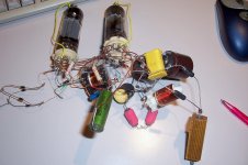
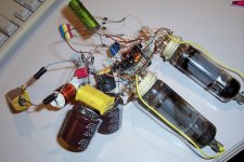
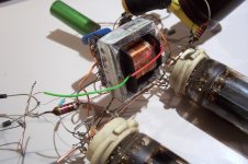
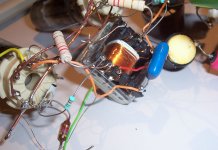
Here is the prototype (yeah, I know, it looks a bit messy, but for some time it worked like a charm
).The transformer is made on a small ferrite EE30, and you can note that I barely used 1/3rd of the available copper window.
Attachments
Gm has nothing to do with it. Gain just means how many volts you drive it with, which is easily achieved through various means (at worst, a transformer, though winding them for good step response at this voltage is difficult).
What is most critical is heater power. Bigger heaters means bigger cathodes means more peak current available. Few tubes were made with excessive emission, and sweeps are the most suitable for this application -- for obvious reasons. If you want to get into the really fancy stuff, you might find some radar pulse tubes that have huge peak ratings, but even then, those were more on the side of EHV pulses, with too little perveance and dissipation to be useful here (not to mention the availability).
Tim
Is it really this thread you intended to answer?Gm has nothing to do with it. Gain just means how many volts you drive it with, which is easily achieved through various means (at worst, a transformer, though winding them for good step response at this voltage is difficult).
What is most critical is heater power. Bigger heaters means bigger cathodes means more peak current available. Few tubes were made with excessive emission, and sweeps are the most suitable for this application -- for obvious reasons. If you want to get into the really fancy stuff, you might find some radar pulse tubes that have huge peak ratings, but even then, those were more on the side of EHV pulses, with too little perveance and dissipation to be useful here (not to mention the availability).
Tim
I don't see what gm has to do with it, or the step response of the transformer for that matter.
a guy in Germany prototyped this animal, also based on PL504;
Schaltnetzteil mit Roehren, von Hans-Martin Sauer
I think it's of a resonant type (plate v is sine), 173kHz, 48W input, 20W output, 40% efficient but the PY82 rectifier takes 6W, with sand efficiency could be some 55% and that includes the PL504's 8W heater which is derived from mains with a cap. Xfrm is air-core ...
Attachments
Last edited:
Well, *all* old BW TVs had a tube driven SMPS inside, the high voltage stepped up to some 15kV by the Flyback ferrite transformer at around 17kHz , rectified by a special ultrafast ultra high voltage diode and driven by some trusty *switching* tube (think 6DQ6) so all the elements are there.
We are talking 50/60 years old Technology.
We are talking 50/60 years old Technology.
- Status
- This old topic is closed. If you want to reopen this topic, contact a moderator using the "Report Post" button.
- Home
- Amplifiers
- Power Supplies
- Sweet folly: a tube SMPS