Let us indulge in a little fantasy.
Many people are against the use of SMPS's in audio.
Other say that tubes are outdated and are worthless compared to solid state.
Here is a project to reconcile them all: a tube SMPS.
This example delivers ~300V @ 60mA, and uses a single pentode.
It operates at 120KHz, and the transformer could even be air-cored.
If a P-series tube is used, the filament can be powered by a capacitive supply.
Just for fun, of course, at present it has only been simulated, not built yet.
Attachments
Amazing ")
This really looks interesting. Good way to spend the tons of PL504/PL36
I'm not really good familiar with SMPS. What kind of circuit is this ? Looks like self resonating (500µ & 4.7n). Where is the green signal measured ?
IMHO it wouldn't be a problem to use Valve rectifiers for the secondary. Fast switching shouldn't be a problem.
interesting idea, but at that frequency it doesnt matter if its valve or SS, your not going to hear anything that its producing for carrier, the 'bad' smps's that people talk about from time to time run on 16~30 kHz which on the lower end is is possible to hear diode switching impulses
Yeah, it is basically a class C power oscillator.Amazing
This really looks interesting. Good way to spend the tons of PL504/PL36
I'm not really good familiar with SMPS. What kind of circuit is this ? Looks like self resonating (500µ & 4.7n).
It is the anode signal of the pentode.Where is the green signal measured ?
Mind you, it is not that inefficient; I pushed the circuit to its limits to get 300V on the load, which wasn't very good for efficiency, but at more modest power level, I had ~60% efficiency (excluding the heater), and tube experts could do much better.t If we should have all this heat and sunusoidal stuff couldn't we put some output voltage feedback on it too?
Inductive coupling could improve the situation, and the oscillator could then be made a blocking one, but this would degrade the relative cleanliness of the signals.
I have also tried Royer versions, which are even cleaner and offer better efficiency (but at the expense of a second valvle).
Some mode of feedback could be included, via the screen grid f.e.
Ooops!Doesn't look like the schematic you posted first.
Sorry, wrong file, this should be the right one:
I think the switching frequency is not the only objection, the internal impedance is another one.interesting idea, but at that frequency it doesnt matter if its valve or SS, your not going to hear anything that its producing for carrier, the 'bad' smps's that people talk about from time to time run on 16~30 kHz which on the lower end is is possible to hear diode switching impulses
Attachments
I recall some of the older Tek scopes using a little switcher in an AL box,for the HV voltages for the CRT.
I might go see if I can hunt down the circuit.
http://i199.photobucket.com/albums/aa154/Nothing40/Random Stuffs/Tek545HV.png
It uses a 6AU5 (V800) and a 12AU7 (V814)
I might go see if I can hunt down the circuit.
http://i199.photobucket.com/albums/aa154/Nothing40/Random Stuffs/Tek545HV.png
It uses a 6AU5 (V800) and a 12AU7 (V814)
Last edited:
Beautiful!
I had toyed with the idea of making an amplifier of that sort, but I had other equally silly projects to waste my time on, and it didn't happen.
But I must admitt, that's exactly the kind of thing I would have strived for. I am not sure I would have succeeded, as my valve skills are rather limited.
Here is an example of what I talked about earlier: a symetrical Royer converter.
This one is a relatively low power, as it's based on a double triode (I gave mistakenly an example with pentodes in the first file I posted, but it's less evolved).
It is more complex than the single ended one, but it does have advantages: first, the efficiency, in this case almost 85% (excluding the heater) and second, the cleanliness: because of the symetry of the circuit, capacitive couplings from primary to secondary will largely cancel, giving a good common interference rejection.
Attachments
Here is an inductively-coupled version of the single-ended oscillator.
The output power is 20W, with an efficiency in excess of 75%.
Not too bad considering the non-perfect (and moderately realistic) parameters of the transformer.
I have also physically tested the Royer version.
It works, but the output voltage is only ~200V, instead of 300V predicted by the sim.
But this is caused by my "transformer": it is a (very) quick and (very) dirty piece of .... work, and when I enter the actual measured parameters in the sim, I get an even lower voltage, ~180V.
I'll post some pics this evening.
Attachments
Last edited:
Since there is no regulation, and therefore no ripple-rejection mechanism, we know that any ripple present at the primary will be reflected practically unchanged at the secondary.Why are you simulating it with perfect DC input?
Adding ripple would fuzzy the waveforms and bring no additional useful information.
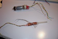
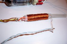
Here is the "transformer"  :
:
It looks like a disaster, and it is one....
I wanted to make real physical tests, but I didn't want to spend two hours making a proper transformer.
It comprises three windings of 250 turns 0.18mm each: the two half-primaries are wound side-by-side on a 7mm dia plastic tube, and the secondary is wound over the whole primary.
I built it this way to make an implicit feeding coil with the leakage inductance between the two primaries.
But I overdid it by a mile: with this coil arrangement, the coupling factor between primaries was barely 0.1, resulting in 1mH leakage instead of the 150µH required.
In addition, the coupling between primary and secondary was a catastrophic 0.7.
With hindsight, I should have sandwiched the secondary between the primaries, this would also have resulted in a less ridiculous length to diameter ratio.
The DC resistance of each primary is 3.6 ohm, and the secondary is 4.4 ohm.
Using this transformer together with a used 12BH7 double-triode from 1963, I was able to get 197V output on a 10K load. The rectifier diodes were BA159.
With the transformer's actual parameters, the simulation gives ~20V less than the real circuit, not that bad after all.
:It looks like a disaster, and it is one....
I wanted to make real physical tests, but I didn't want to spend two hours making a proper transformer.
It comprises three windings of 250 turns 0.18mm each: the two half-primaries are wound side-by-side on a 7mm dia plastic tube, and the secondary is wound over the whole primary.
I built it this way to make an implicit feeding coil with the leakage inductance between the two primaries.
But I overdid it by a mile: with this coil arrangement, the coupling factor between primaries was barely 0.1, resulting in 1mH leakage instead of the 150µH required.
In addition, the coupling between primary and secondary was a catastrophic 0.7.
With hindsight, I should have sandwiched the secondary between the primaries, this would also have resulted in a less ridiculous length to diameter ratio.
The DC resistance of each primary is 3.6 ohm, and the secondary is 4.4 ohm.
Using this transformer together with a used 12BH7 double-triode from 1963, I was able to get 197V output on a 10K load. The rectifier diodes were BA159.
With the transformer's actual parameters, the simulation gives ~20V less than the real circuit, not that bad after all.
Attachments
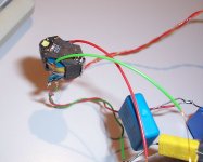
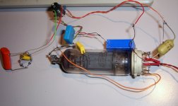
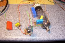
I have built the inductively-coupled version.
This time, I learned my lesson and made a "proper" transformer, on A RM ferrite core, material N41: see picture Xformer.
It is minuscule, smaller than the tube socket in fact.
The tube is a 27GB5, as I don't have EL34's, and it isn't exactly new, as can be seen from the photo's. It is also from the '60s.
The 27GB5 is high voltage tube and has higher internal resistance than the EL34, but despite those handicaps, the circuit was able to put a healthy 275VDC out on a 5K load. Not bad.
I had to split the tuning cap between the primary and secondary to share more evenly the resonance current between the two windings.
Otherwise, the reality and sim agreed quite well. I could find a model for the 27GB5 unfortunately.
Attachments
Since there is no regulation, and therefore no ripple-rejection mechanism, we know that any ripple present at the primary will be reflected practically unchanged at the secondary.
Adding ripple would fuzzy the waveforms and bring no additional useful information.
Sorry about the stupid question but I don't know anything about smps. How would your circuit be used to get 300V DC from 120V AC?
Sorry about the stupid question but I don't know anything about smps. How would your circuit be used to get 300V DC from 120V AC?
On 120V you'd probably use a voltage doubler and plenty of capacitance to provide the required DC to the SMPS, the transformer winding ratios would be chosen based on the plate swing available in order to achieve approximately 300Vpk on the secondary.
- Status
- This old topic is closed. If you want to reopen this topic, contact a moderator using the "Report Post" button.
- Home
- Amplifiers
- Power Supplies
- Sweet folly: a tube SMPS