For Screen drive of the 6CB5, one will need around 3.8 (internal Mu) times as much AC drive signal as would be used with g1 drive alone. (and handle the screen current too.) So that needs to be a HV capable follower, and the driver stage needs to be able to develop that AC as well.
Tell me about it: I'm experimenting with a PP EL36 setup. Added to the high g2 drive requirements the OPT has 20% CFB windings.
G1 drive gives me about 30W output, G2 drive yields a whopping half watt

I definitely need more volts there.
Ahh, OK, Pete's buffer is the conventional design with an N type follower Mosfet.
If someone can locate SpreadSpectrum's P follower schematic here, that would be safer, since the CCS pull-up limits the screen current.
Would be just a HV P channel Mosfet, with drain to ground, and source to the CCS (CCS from B+ or some reduced B+). Biasing done on the gate side. Direct coupled source to the tube screen (include stopper resistors for screen and Mosfet gate too). Failure of the Mosfet (to a source-drain short) turns the tube off. Down-side of the P channel design is approx. 2X input capacitance to drive the P Mosfet versus N type.
With such expensive OTs, I would try this all out with some cheap console or guitar OT first!!
The combined g2 +g1= g2/Mu, or the g2 +Schaded g1, schemes would still be safer as far as preventing tube meltdown or arc-over with extended usage. However, George found that if the screen grid gets hot enough, it can start emitting electrons. This COULD possibly combine with a shorted P Chan Mosfet follower to drive high current through the tube plate. So the P channel follower may be less likely to reach tube failure via screen current limiting, but if it does, its worse. I guess a diode in the screen lead could prevent that reverse current disaster.
"G2 drive yields a whopping half watt "
Pain.....
Last edited:
Note:
SpreadSpectrum has done a screen drive follower using a P channel Mosfet, where it pulls DOWN (instead) against a CCS pull-up to B+.
That's an interesting idea, but it isn't mine. I just did an amp that was conventional g1 drive with a p-channel follower that drove a feedback divider. See here for a write-up: Tube Amps with a Twist: A Push-Pull Amplifier with Simple Plate-Grid Voltage Feedback Driven by a P-Channel FET
I would build a similar amp if I had another amp to build and conventional output transformers. It was easy to make and worked extremely well.
I ran those in normal pentode mode but I did have a current-limited screen regulator. I just used an n-channel mosfet follower with a BJT that would pull the gate voltage down and sag the screen if the tubes drew too much screen current. It wasn't really necessary since I operated the tubes in a way that shouldn't tax the screen much, but I figured it wouldn't hurt and could save something else if I had a tube go bad or something.
Something similar could be done on a screen driver. You could use an n-channel mosfet as a screen driver and set a BJT current limiter to set a current limit. I'm not sure how much distortion would be introduced. Testing the concept would definitely be in order to see if you can get a reasonable current limit without adding much distortion.
We are definitely covering some new territory here with all these unconventional ideas. I'm sure a good solution can be found, but it may take some trials to "settle in the groove".
Putting a current limiter in the drain side of an N channel follower could limit the output (source) current, but if the driven tube has gone haywire already, it might pull the screen to a voltage outside of the gate drive range. A protection diode on the Mosfet could protect the gate, but it then sends the out of range voltage back to the driver tube. Needs some looking into, don't want the whole amp to cascade fail.
One thing that would be useful to know is whether at the same Watt output level, does screen drive have more crossover distortion than the g1 drive? (assuming biased for the high power output, or for the same max power output) George maybe has some thoughts or data on this. All this 300 Watts from two 6CB5s stuff is breathtakingly impressive, but does it still sound good?
Last edited:
"G2 drive yields a whopping half watt "
Pain.....
Yeah, I just saw the internal mu of 5,6.
So I'd need more than 300 Vrms per screen grid to drive it full
Without the CFB it would be more doable.
Considering other sweeps. How do you determine the internal mu when it is not listed in the datasheet?
With such expensive OTs, I would try this all out with some cheap console or guitar OT first!!
I'd like to build something modest here, and if I can wrap my head around it, then go for something a bit more wild in concept. I have heard that sweeps run in straight pentode with proper NFB actually sound very nice. Thomas AKA Vinyl Savor seemed to really like the 6CB5A for sonics.
Last edited:
Some of the data sheets have a curve set of plate current versus grid 1 voltage (bottom axis), with stepped g2 volts. Looking across at a constant current, determine the delta in g2 voltage versus delta in g1 voltage. deltaVg2/deltaVg1 = Mu
example 6AV5 data, top of page 4:
http://frank.pocnet.net/sheets/093/6/6AV5GA.pdf
I have a list of many of the common sweep tubes here if the data sheet doesn't give a clue.
Here is a list:
http://www.diyaudio.com/forums/tube...nificent-television-tubes-38.html#post4160155
example 6AV5 data, top of page 4:
http://frank.pocnet.net/sheets/093/6/6AV5GA.pdf
I have a list of many of the common sweep tubes here if the data sheet doesn't give a clue.
Here is a list:
http://www.diyaudio.com/forums/tube...nificent-television-tubes-38.html#post4160155
Last edited:
Well, there is certainly nothing wrong with pentode mode, just needs some form of local or global Fdbk to lower the output Z and distortion. Pentodes are capable of lower distortion than triode mode in most cases, since resistive derived feedback is more linear that the internal triode Fdbk (when a load is applied certainly).
Applying local feedback of some form is quite useful for cheaper OTs, since it can improve their performance. For the high quality OTs, global Fdbk alone can work quite well. Some of the best known amplifiers used both local and global feedback, like Citation II or McIntosh etc.
For local Fdbk, many choices: CFB, Schade, plate to driver grids, plate to driver cathodes, even plate to driver screens (special driver Vg2/Vp conditions). Combinations have been used as well.
Schade or Fdbk to driver grids or cathodes are the easiest. Fdbk to driver grids or cathdodes will give the lowest distortion, but may be clinical sounding if over-done.
Here is an RCA 50 Watt amp that used both Schade and Fdbks to the driver cathodes to linearize the pentode driver V to I conversion for the Schade setup.
Attachments
Last edited:
All this 300 Watts from two 6CB5s stuff is breathtakingly impressive, but does it still sound good?
300 watts from a pair of 6CB5's.....180 watts at 4% distortion is a real number. Adding 10 db of overdrive produces near square wave output with overshoot caused by the OPT. The HP audio analyzer can not be trusted under these conditions, but the big numbers sound cool.
I have built three of Pete's red boards at the 125 WPC level. These are conventional G1 drive sweep tube amps. I use the Plate to Plate feedback built into the design (commonly called Schade after the 1930 publication where it was first mentioned). No GNFB is used although the board supports it. These amps sound very dynamic with big clean bass.
A screen driven sweep tube amp will typically have a higher output impedance than a G1 drive amp with the same tube at the same power level. It will also typically have far less crossover distortion and is usually happier at a much lower idle current resulting in higher efficiency. I have usually been able to make a screen drive amp work with only Schade feedback, no GNFB. Screen drive only works with sweep tubes and a few others that have low voltage requirements for G2. Attempting to drive a common audio tube like a KT88 via the screen would require about 400 volts P-P of drive.
A dual driven amp will have a higher output impedance that a G1 driven amp, but its output impedance can be higher or lower than a pure screen drive amp with the same tube. This depends on the tube's characteristics and the ratio of G1 VS G2 drive. Dual drive can work with common audio tubes. I have made dual drive work with KT88's. Applying enough Schade feedback with the KT88 resulted in a reduction of gain such that I couldn't get enough drive voltage. GNFB worked best.
I had a nice little dual drive amp working with a pair of tiny output tubes that made about 50 WPC and sounded delicious, and a bigger one with 13GB5/XL500's that made over 100 WPC. Unfortunately they both got tossed into a box over a year ago, and haven't seen daylight since.
Job loss, two moves, one of 1200 miles, daughter, her husband, and 4 grandkids coming to live with us, and 3 of us out looking for suitable employment, hasn't left any time for tubes, but hopefully soon.........
Ohh, so 180 Watts in the linear region. My eyes almost popped out when I saw 300 Watts from 2 6CB5s.
Yeah, I can imagine that trying to Schade the g2 drive directly would make the driver requirements go exponential.
Putting the Schade back to the g1 in the combined g2 and scaled g1 setup looks workable. SpreadSpectrum was descibing his P channel driver for Schaded g1 in another thread. Which developed a large voltage from the driver stage with a Mosfet buffer, to go through a large value resistor to make it look like a current source into the Schade network. Seemed logical to just add a direct connection from the Mosfet follower to drive g2 as well. Combines two linear drive modes and gets lower output Z.
Hope you all can get settled in there in WV soon. I came here to NC 10 years ago thinking I would only stay a short while, so I've been renting forever now.
Time to make decisions and eventually buy a retirement home somewhere. I like the white water kayaking, hiking, lakes and mountains here, but summer just gets too hot and humid for me. I guess the lack of snow in winter is compensation, but I used to enjoy the exercise shoveling the stuff. Now we all wear wetsuits and go kayaking in January instead. Or hiking.
Last edited:
Aren't the socket cutout holes for Novar the same or similar as Octal or Compactron?
Here is a Schade (Fdbk back to the driver cathodes) +CFB schematic, the ARC D51
I would just consider it an idea model, from the driver to the outputs. The input stage is hideous. The CFB using the secondary is probably more marketing than useful, since the plate feedbacks may have more gain and will over-ride the CFB.
On second inspection, looks like they made the plate feedback resistors so high in value that the Schade and secondary CFB loop gains may be comparable.
Attachments
Last edited:
That is interesting. I do need to be careful with the driver size. I will run out of real estate quickly. You are correct, I can put octal sockets in place. Glad you mentioned that. I can use 12SN7s or 6SN7s there.
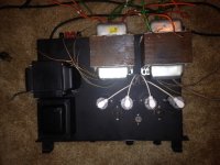
The power transformer is the chassis mount through design, and the choke is a Hammond 193Q rated at 500mA and 10H. I can most likely get away with modest filter capacitors since the choke is so big. I have to use a doubler to get the B+ up where I can get decent power unless running them on ~350V on the plates will still give good results.
The power transformer is the chassis mount through design, and the choke is a Hammond 193Q rated at 500mA and 10H. I can most likely get away with modest filter capacitors since the choke is so big. I have to use a doubler to get the B+ up where I can get decent power unless running them on ~350V on the plates will still give good results.
Attachments
CFB from the OPT speaker winding with push pull is highly dependent on the OPT. I have used CFB on many SE amps, and it is one of the options in an SSE build. It works wonders with some OPT's (small Edcors) and makes marginal improvements in others (really good ones), but I have never seen CFB make an amp measure worse than no feedback.
This is not true with push pull amps. If the OPT is not reasonably symmetrical from half to half, using the speaker terminals for CFB as shown in this ARC amp, can make performance measurably worse, and even invite instability. This is especially true at the frequency extremes.
This is not true with push pull amps. If the OPT is not reasonably symmetrical from half to half, using the speaker terminals for CFB as shown in this ARC amp, can make performance measurably worse, and even invite instability. This is especially true at the frequency extremes.
If the secondary has a different # of turns between the 0 to 4 Ohm taps than between the 4 to 16 Ohm taps, it certainly won't work well in P-P. Then there is the assymetric loading issue with an 8 Ohm load.
Using the secondary for the CFB winding also puts significant phase shift in the local loop due to the OT leakage L and load current. A separate primary CFB winding is better.
If the OT has primary UL taps, these are usually well coupled to the secondary (for UL stability and accuracy). So taking Fdbk from the UL taps (to the driver stage) can work well for low distortion, providing the local Fdbk loop stays stable with the extra driver gain. There could be some phase shift between the plates and the UL taps from distributed capacitance.
An interesting Schade setup would be the RCA 50 Watt Schade design approach, but with the feedbacks taken from the UL taps instead. Or could go all the way with UL Fdbks back to the driver grids (crossed, a'la Thorsten's design) or to the driver cathodes (like the ARC).
I'm puzzled by the RCA design, since just using the Fdbks to the cathodes should provide more local loop gain without the Schade connections to the driver plates too. But maybe the designer tweaked the two pathes while watching an FFT analyzer. (doubtful though) The RCA gets 0.1% distortion though.
The Citation II also has peculiar Fdbks too. Output and driver Schade Fdbk pathes back to the driver grids.
Two Fdbks to the same point cannot both be satisfied. So some tweaking must have gone on there too. Would be interesting to hear the designer's rationale for both designs.
Attachments
Last edited:
A Thorsten Loesch type "local" feedback design by Ray Moth (I haven't found the original Thorsten L link yet) I think it needs some DC isolation caps on the 6SN7 grids yet.
"Local" Fdbk in these contexts meaning: not including the OT in the loop. "Partial" Fdbk might be a better description for these. (more traditional Local Fdbk means just a single gain stage in the loop. )
http://www.diyaudio.com/forums/tube...al-fb-decent-damping-factor-5.html#post517524
One could also take the Fdbks from the UL taps in this type of design.
Attachments
Last edited:
A few comments needed yet about the Ray Moth/ Thorsten L design above.
Thorsten made some comments on the advantages here:
http://www.diyaudio.com/forums/tube...al-fb-decent-damping-factor-5.html#post525580
But some disadvantages should also be mentioned.
The Fdbks to the driver grids lower the impedance at the driver grids, making for loading on the 1st input stage (or the splitter). One usually likes to be able to use a CCS load on the input stage. I guess a Concertina splitter would not be bothered by the low Z load, since it acts like a buffer anyway.
The driver stage needs to be a real differential stage (CCS tail) due to the crossed Fdbks, if the output stage is running in class AB. Reason being that when one output tube cuts off, the other active output tube's N Fdbk is crossed over to the dead P-P side. So no correction will occur in the actual active output (except for phase lagged signal THROUGH the OT from P to P), unless the driver is differential, to spread the correction to both P-P sides.
Ie, a class B output (moment) without a differential driver would periodically cut the direct feedback off. The momentarily un-driven side of the P-P primary does however still act like an unloaded CFB winding with good coupling to the output. So the N Fdbk is dynamically varying the amount of resistive winding loss (from load current) injected into the correction process. A more consistent N Fdbk could be obtained using the earlier mentioned scheme of 40% CFB using crossed UL taps for the cathodes, since each tube would always be driving BOTH UL winding sides. (assuming the N Fdbk tapped from the UL taps then.) This issue applies to any of the schemes using plate or UL feedbacks.
But then, once you have a differential driver stage, one doesn't really need a splitter anymore. So back to the loading issue on the input stage then.
So every scheme has its plus's and minus's.
Last edited:
Corrections.......................
A closer inspection of the winding loss effects in the P-P plate or UL partial feedbacks makes it clear that the class A opposing (cancelling portion) current/winding effects cancel out (with a differential driver), so that one is left with one Fdbk having the expected tube drive current*winding Ohm effect, and the other Fdbk effectively not. (so only the active net drive current * Ohms shows up steadily) So then the average of active and in-active tube Fdbks is taken by a differential driver stage. No strange modulation of winding loss is taking place after all. That should be OK. One does still want a differential driver stage to get that consistancy.
So the partial (or "local") Fdbks to a (differential) driver stage looks like a good design, just low impedance inputs to deal with for the Fdbks to the driver grids case. Easy to do like the other partial feedback schemes.
Also, on the Citation II, with two "local" or partial feedbacks back to the same driver grids, I may be wrong about not being able to satisfy both demands. Just think of the two feedbacks as summed linearly. One then gets a linear summation of corrections for both error terms. Each offending (distorting) device in the forward path gets its correction allotment in sequence, with the remaining correction term passed on to the next offending distorter. So I'm adding the Citation II configuration to the list of well understodd partial feedback schemes.
The RCA 50 Watter one is still a mystery to me as to why they stuck the short path Schade Fdbk into the larger driver cathode Fdbk loop (reducing the outer loop gain quite a bit). Have to think about that one some more. If the gain reduction in the larger cathode loop were the same as the smaller Schade loop gain added, then it would be a no effect trade-off. But the plate resistor loading is burning some unused gain. Maybe that can be fixed up for the RCA design.
Last edited:
- Status
- This old topic is closed. If you want to reopen this topic, contact a moderator using the "Report Post" button.
- Home
- Amplifiers
- Tubes / Valves
- Sweeps in class A