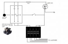
Next question ") the coil connects to the AC line on one side, to the transformer on the other... and not directly to the other side of the AC supply.
the coil connects to the AC line on one side, to the transformer on the other... and not directly to the other side of the AC supply.
So when it's on and working what actualy is the coil voltage ? is it full 120 vac or does the tap/winding on the tranny give a lower value ?
Have an idea you see
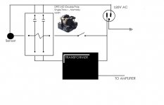
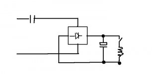
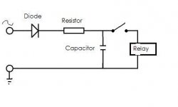
Would something like this work... the diode/resistor and cap produce a DC supply. The coil is now powered by this. The resistor would be chosen to give the required coil voltage when on. You would have to see if heat would be an issue... perhaps a bit of trial and error to determine what works best. The cap would be at a guess around 100uf ? perhaps even less would be OK 68uf or 47uf.
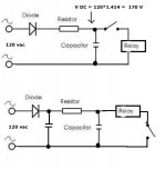
Or, you could isolate the coil supply altogether. Use a "wattless dropper" (capacitor) which dissipates no power to limit current. Feed a bridge rectifier with smoothing cap as before. The relay gets a huge "kick" to pull in cleanly (cap at AC peak volts) and the current is then limited by the wattless dropper thus reducing the coil voltage.
the coil connects to the AC line on one side, to the transformer on the other... and not directly to the other side of the AC supply.So when it's on and working what actualy is the coil voltage ? is it full 120 vac or does the tap/winding on the tranny give a lower value ?
Have an idea you see
Would something like this work... the diode/resistor and cap produce a DC supply. The coil is now powered by this. The resistor would be chosen to give the required coil voltage when on. You would have to see if heat would be an issue... perhaps a bit of trial and error to determine what works best. The cap would be at a guess around 100uf ? perhaps even less would be OK 68uf or 47uf.
Or, you could isolate the coil supply altogether. Use a "wattless dropper" (capacitor) which dissipates no power to limit current. Feed a bridge rectifier with smoothing cap as before. The relay gets a huge "kick" to pull in cleanly (cap at AC peak volts) and the current is then limited by the wattless dropper thus reducing the coil voltage.
Attachments
That's a bit of an odd circuit looking at it
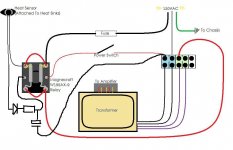
I agree with Mooly 100%. What's bugging me is the wire from the power switch to the transformer. Now in my mind that can't be any part of the transformer winding simply because there is no way to pull a load of current through the relay coil & feed the transformer.
I think it's much more likely to be some kind of thermal switch embedded in the transformer, so like the heatsink sensor it'll open if the transformer gets too hot, thus shutting the amp down in the same way.
I could be wrong though
That's a bit of an odd circuit looking at it
omg this made me actually lol
I can see where a schematic would have been useful here..
I think maybe you guys are looking at this wrong.(or I could be) First off, the black/red colors of the actual wires are in opposition of +/- I think.
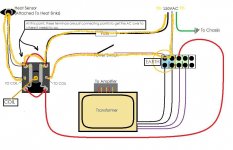
First I'll highlight the flow of AC to the coil.
Then the AC flow for the xfmr.
Also just takin' a stab at a block diagram for clarification.
Attachments
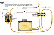
Updated schematic
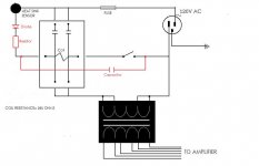
arrrrgh, can't edit this now. Anyway I hope y'all know I was laughing at the noobishness of my own drawings. The original drawing shows 2 windings paralleled and the switch at the earth end of the AC line, all connected at the same common point on the connecting block (highlighted blue). When the switch is thrown, the AC travels to the 2 "purple" windings that are also paralleled on the connecting block (highlighted light green) then into the transformer. There are actually jumpers across those paralleled areas, I just left space in the lines and used highlighting to show the common connections. There are 4 total windings connected to the block, and 6 total windings coming out of the transformer that go to the amplifier (rectified/ground/power caps etc).
I just updated the diagram to show this. see below
Attachments
The important thing is what the relay sees across the coil... and you last drawing is more "conventional", showing the coil straight across the line voltage.
I would try the simple DC solution for starters.
And a wattless droper something like this. The cap charges to Vac peak again but as soon as the coil is connected the cap feeding the bridge limits current flow.
It would all be trial and error... you would have to rig it up to experiment on.
I would try the simple DC solution for starters.
And a wattless droper something like this. The cap charges to Vac peak again but as soon as the coil is connected the cap feeding the bridge limits current flow.
It would all be trial and error... you would have to rig it up to experiment on.
Attachments
Cool. So is this kinda like a "cold" way to drop the voltage going to the coil?
This info/link look similar?UK Vintage Radio Repair and Restoration - Dropper Calculations
The closed loop in your drawing is the relay coil, and the two points going to the left is the 120v going to the amp, correct?
So, I shouldn't try to just use a resistor alone to lower voltage
off to work-I'll check back later
Thank you!
A resistor alone would still provide AC to the coil.
You have to rectify and smooth to get DC... and a silent coil.
Heat is the only real drawback to the resistor... but it's easy to try... and well worth experimenting with as the coil will hold the relay closed at much lower voltages than the pull in voltage.
You have to experiment... try say a 1K, 1K5, 2K2 etc (of an appropriate wattage) and see what the coil settles to voltage wise, and see if it's viable.
Having proved it works, try the wattless dropper approach.
That link of yours explains it... it's an old old technique.
In my diagram it's mains in at the left
Thanks guys. I'm not sure I understand the layout of this circuit though. Could you help clarify? Looking at Moolys drawings and the "heater" drawings on that link, I'm a little confused This cap is going across the coil, rather then in-line....
Is this (highlighted in red) correct - below?
I also think the cap might need to be connected before the switch, not after....?
This cap is going across the coil, rather then in-line....Is this (highlighted in red) correct - below?
I also think the cap might need to be connected before the switch, not after....?
Attachments
Last edited:

I know this is stupid but why not eliminate the relay all together and put in a 15 or 20 amp on/off switch. Since your amp runs of 117 volts ac , unless it is plugged into a "special " 20amp 117vac socket with appropriate breaker and wiring, it will never draw 20amps of continuous current. Typical breakers in NA are 15 amps for a total maximum draw of 1775 watts. No relay = no relay noise. Put a RC network across the switch contacts to eliminate arcs at turn on. If the amp is for home use, bypass the on off switch and relay, plug the amp into a power bar/surge protector and use the on off switch on the power bar to turn on the amplifier. That's what I do at home.
I know this is stupid but why not eliminate the relay all together and put in a 15 or 20 amp on/off switch.
It's a great idea
The only downside I can see would be phsically fitting it neatly... cutting holes and all that.Pure_brew,
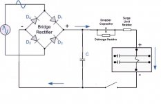
Your first drawing is correct. The cap charges to around 170 volts DC when the switch is open. This means when you close the switch the relay sees this full DC voltage and pulls in sharply, and then as the cap discharges the voltage across the relay falls as it is limited by the resistor.
Problems are that the relay is an unknown quantity... what value resistor/s (you might be better with two or so in series to enable lower wattage parts to be used) can you get away with. That's why I say just rig it up and experiment. You are looking at using say 1k 3 or 5 watt resistors at first to just get a feel for what happens and what the voltages settle at. The cap affects it too... we don't need super smooth DC, just smooth enough that coil noise isn't an issue.
The second drawing won't work at all.
First the droper cap is on the DC line... so no current flow.
Also the cap across the bridge needs to be where the coil will get the full voltage across this cap applied to it initially a switch on.
(breaking out the safety glasses)
Well I see I would need to experiment. I tried on the bench for the heck of it a 1.3k resistor 15w (had one laying around) with 120v alone on the relay. Coil chatters like a set of wind-up teeth.
Anyway the thing that looks wrong to me in the drawing, is that cap goes directly to earth, so there's quite a potential for shock. Also if I put the connection point on the inside of the left of the switch in the drawing, the cap would have to "bleed off" in order for the relay to fully release- which it would, but not immediately, since the coils resistance is 290ohms. I guess I don't understand the flow.
Is this how it flows, in a simpler layout?
Attachments
Last edited:
A resistor on it's own and it will chatter. You need the diode and cap.
Looking at your diagram post #24 and the switch terminal (one of them) has line voltage on it... so I don't quite follow you saying "is that cap goes directly to earth, so there's quite a potential for shock". The cap does have 170 vdc on it. It probably makes more sense to swap the switch and relay so that the switch is now in the "earthy" end of the circuit.
Are you sure that one end of the AC input is grounded ? anyway or can the mains lead be connected either way round ? This is where local differences come in. In the UK the neutral and earth can often be regarded as one and the same potential wise, although of course they are very different in the way they are configured and their purpose.
The diagram you have done above is fine... one thing I thought of though was adding a second cap as here. The one at the other side is still needed to give the relay a good "kick" to switch cleanly.
Attachments
I know this is stupid but why not eliminate the relay all together and put in a 15 or 20 amp on/off switch. Since your amp runs of 117 volts ac , unless it is plugged into a "special " 20amp 117vac socket with appropriate breaker and wiring, it will never draw 20amps of continuous current. Typical breakers in NA are 15 amps for a total maximum draw of 1775 watts. No relay = no relay noise. Put a RC network across the switch contacts to eliminate arcs at turn on. If the amp is for home use, bypass the on off switch and relay, plug the amp into a power bar/surge protector and use the on off switch on the power bar to turn on the amplifier. That's what I do at home.
I still have to do work to figure out a filter anyway, which is an issue for me mainly either way. Plus finding a replacement switch that fits into the cut-out/etched thick aluminum front panel would most likely devalue the amp alot (not that I'm planning on selling it
 )
)A resistor on it's own and it will chatter. You need the diode and cap.
Looking at your diagram post #24 and the switch terminal (one of them) has line voltage on it... so I don't quite follow you saying "is that cap goes directly to earth, so there's quite a potential for shock". The cap does have 170 vdc on it. It probably makes more sense to swap the switch and relay so that the switch is now in the "earthy" end of the circuit.
Are you sure that one end of the AC input is grounded ? anyway or can the mains lead be connected either way round ? This is where local differences come in. In the UK the neutral and earth can often be regarded as one and the same potential wise, although of course they are very different in the way they are configured and their purpose.
The diagram you have done above is fine... one thing I thought of though was adding a second cap as here. The one at the other side is still needed to give the relay a good "kick" to switch cleanly.
Well I guess I'm not thinking correctly. I was thinking in a bench arrangement, like the one below, that the cap could discharge to a person if this example was unplugged (switch closed), after being charged up for awhile. Then if the ends of the power cord was touched, would the cap(s) drain to the hand......
This is because I haven't worked with diodes before, but if a diode only allows electricity to flow in one direction ----->l , then I guess its safe after its unplugged, since I couldn't come in contact with both ends of the cap(s).
Even then, it looks like the load would drain off the cap(s). So potentially, the diode would have to *fail closed* or allow reverse voltage.
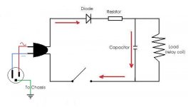
This makes me think that when I add a switch to this, I should have it located well before the circuit like here below. However, the cap(s) will of course not be pre-charged, but will receive in-rush current (well, there would be in-rush current at plug-in anyway if the switch was placed after the cap(s) as previously proposed).
I hope this arrangement clarifies: live [red], neutral [blue](return path, also referred to as ground), and ground [earth]
The rest of the amplifier, is grounded to the chassis [earth] after the transformer. This circuit, is connected to live [red] and neutral [blue].
So, the AC power going to the switch, relay and the transformer are all fed with the polarized live/neutral lines FYI. You could reverse polarity on the AC cord end, but not without foolishly cutting off the ground. The cord only looks 2 prong, which is what I'll use on the bench, but the actual amplifier cord is 3 prong with the ground/earth going straight to the chassis.
Peace
Attachments
Last edited:
I understand what you are thinking now.
You could therefore add a bleed resistor across the cap around 470k or so in value. It would have to be a resistor suitable for high voltage use though. Resistors do have a max voltage rating even though the power dissipation may be well below the maximum.
Much commercial gear such as DVD/VCR/TV etc all use switch mode power supplies. These connect the mains directly to a bridge rectifier that has a large (100 to 470uf) cap across it. I have never come across a failure that gave a shock via the mains lead (I have worked on 10'000's of these over the years)
Strange to say what does give a shock... particularly on 240vac is when manufacturers have a small 0.1 or 0.22uf cap directly across L-N before the switch as this can be charged to around 340 volts
Once again, switched and/or fused AC power neutrals are dangerous and probably not legal.
It's as per the original diagram in this post. The switch isn't switching mains directly... it's switching an internal supply within the amp (the relay coil).
- Status
- This old topic is closed. If you want to reopen this topic, contact a moderator using the "Report Post" button.
- Home
- Amplifiers
- Power Supplies
- Swappin' Mech Power Relay for Solid State