Not quite sure I understand the last question
The signal parts of the amp don't have to be mains grounded at all. They may or may not be... or may be tied via a resistor even. No current should flow into the mains ground, it's purely a safety feature. If the case of the amp became live due to a fault, then the current flows into ground and the resulting overload blows the fuse.
When signal grounds are connected to the mains ground is when "ground loop" problems occur, which can cause hum etc.
Right, there is nothing connected to the mains except for the transformer, relay and power switch.
In this amp, which may be slightly different then other layouts-Everything else is attach to the bus-bar. You can't see it in the pic, but it goes across the bottom of every cap, wraps around the inside of the chassis which I believes picks up other connections on the back-side of the amp. A variant or alternative of "star" grounding maybe?
Since this bus-bar is also bolted to the chassis itself, I guess I thought that voltage traveled though this somehow and went to earth via the outlet/safety ground- lol?
I can see the purpose a little more clearly on safety ground though. If indeed there is a fault, the voltage has a different place to go - instead of through the person touching it. In my case, with the added dropper circuit, the actual safety plug insures proper polarity (I tested the outlet first).
The buss bar is a good solid ground for audio signals.
Lets not confuse mains safety earth and audio grounds")
The audio grounds (the buss bar) carry currents... signals, speaker returns, whatever. All that works independantly of connecting it to the mains safety earth.
A totally mad analogy.
You have a metal bodied torch... a Maglite.
That torch, and the currents within would be totally unaffected if you connected a wire from the body of the torch to the mains earth. It works with or without. Same for the audio. No current flows in the ground wire.
You then take another torch... one that uses more batteries say, and do the same to that adding the ground wire to the mains. No current flows in that lead either. And you can "connect" the torches together (which would be the interconnects) in an audio system.
We'll leave it that because, that opens the door to audio ground loops and hum caused by making that "loop".... which is another subject on it's own
Lets not confuse mains safety earth and audio grounds
The audio grounds (the buss bar) carry currents... signals, speaker returns, whatever. All that works independantly of connecting it to the mains safety earth.
A totally mad analogy.
You have a metal bodied torch... a Maglite.
That torch, and the currents within would be totally unaffected if you connected a wire from the body of the torch to the mains earth. It works with or without. Same for the audio. No current flows in the ground wire.
You then take another torch... one that uses more batteries say, and do the same to that adding the ground wire to the mains. No current flows in that lead either. And you can "connect" the torches together (which would be the interconnects) in an audio system.
We'll leave it that because, that opens the door to audio ground loops and hum caused by making that "loop".... which is another subject on it's own
Actually a decent analogy ty.
Agreed. Cable TV/coax installation + Home Theater= home theater installer must find the loop issue (usually poorly or ungrounded coax distribution) That's all I'm sayin
Ahem*Cough*....
Back to the DC filter. Seems to make sense to insert it right between the mains and the transformer, replacing the terminal block that's currently in place.
We'll leave it that because, that opens the door to audio ground loops and hum caused by making that "loop".... which is another subject on it's own
Agreed. Cable TV/coax installation + Home Theater= home theater installer must find the loop issue (usually poorly or ungrounded coax distribution) That's all I'm sayin
Ahem*Cough*....
Back to the DC filter. Seems to make sense to insert it right between the mains and the transformer, replacing the terminal block that's currently in place.
Back to the DC filter. Seems to make sense to insert it right between the mains and the transformer, replacing the terminal block that's currently in place.
Worth a try for sure
I think this is it (Back on topic)
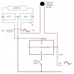
Take a look at this layout. Does this look ok to you? The grounding (-) looks so dramatically different then the diagram but I think this is right. I'm trying to lay this out so I can put it in the amp and close it up.
Thanks
Take a look at this layout. Does this look ok to you
? The grounding (-) looks so dramatically different then the diagram but I think this is right. I'm trying to lay this out so I can put it in the amp and close it up.Thanks
Attachments
Last edited:
Great thank you. Its in the amp now! When I get my hands on the camera I'll show you.
It's completely non-evasive. The board is bolted in an upright position with the resistors being closest to the perforated top panel and away from anything where heat could be an issue. It's all point to point on the board lol, looks like a speaker crossover. I mounted a barrier strip to the board, and everything is connected with eyelets.
So, I can literally remove this, and you would never know it was there. The board is even mounted on the sidewall with the original screw holes, I just used some longer ones.
Thanks for all the help, this works sweet.
I'm thinking about adding fuses (on the incomming AC and the outgoing DC to protect the relay). Seems like a safe and prudent approach. I'm not sure on the values but I think I'm looking at about 125v 100ma. With the initial feed to the circuit, we get a very low current with 170v on 4000 ohms. However, as 2k ohms is acceptable for the circuit, that would put this around a 100ma load.
The 290ohm coil stated operating voltage (min) is also around 100ma @120v AC. While I am way below that, this should be safe. Usually it runs at 120v AC- 290ohms which is around 400 ma constant. But that is AC. The DC version of this runs at 24v - 290ohms which is equivalent to 100 ma.
100 ma seems safe anyway I look at it. If I keep popping fuses on the in-rush (600ma on 170vdc - 290 ohms), then I'll have to raise another 100ma? Should I be looking at slow-blow maybe?
If you want to add a fuse (you only need one) just add it in series with the supply to the diode. You can try 100ma but remember there is the switch on surge (low as it is) of the first 47uf cap. The relay "surge" doesn't really come into it as it's a series circuit and the 4k resistor sets the max current. The relay does see a current spike... but that's not reflected in the AC current draw in the same way. It's just the second cap discharging into the coil (and initially charging via the 4k).
So an anti surge fuse... yes.
So an anti surge fuse... yes.
Well I tried a couple fast blow 100ma and 200ma. They all blew from the in-rush as soon as I plugged in the power cord, no surprise. I couldn't find any slow-blow types in those values locally, except for some 315ma. The 315ma slow blow works and holds fine.
I also discovered an interesting phenomenon...
Due to the low operating voltage I'm using for the relay, if there is a power loss when the amplifier switch is turned "on", what ever is left in the caps will discharge across the coil. Then the relay will release and remain open.
So, when the power comes back on, the relay will still remain open with the amplifier switch still in the "on" position. This is because the cap never had the chance to build up a snap-closing charge, as the circuit itself is still closed allowing voltage, but only low voltage, to pass though the coil which is not enough to close it.
Soooo....In order to actually get the amp to turn on now at this point, is to turn the amplifier switch to the "off" position, to allow the cap to charge up to high voltage, then switch it back again to the "on" position.
While this could provide a false sense of security for overall surge protection, It would appear that this does indeed provide a bit of safety from utility issues that can occur during power losses and restoration. Maybe even "brown-outs" would be less of an issue if the operating voltage is set low enough to cause the relay to re-open itself.
While this may be nothing new, (new to me though) I thought this was a very interesting feature of this circuit.
Are power "glitches" a problem where you are ?
There's no real fix for that. If glitches are always of a small time duration (10's of milliseconds at most) then using larger caps might help.
Not 100% sure about that. I'm speaking about a complete power outage, which is not uncommon during the winter months especially due to weather. Lots of trees
.I have no complaints. I actually think that if the relay opens and wont re-close on its own that it's a good thing. Since the recommendation from the manufacturer is to leave the amp on at ALL times, if the power goes out completely when I'm at work or whatever- then that's just fine with me. You know what I mean?
Last edited:
I know this is an very old thread, but I had this same problem with my 200c and thought this might help someone else out. A friend who works in the field told me that most Magnacraft relays are noisy and to try a Potter & Brumfield relay. The cross-reference on their site said a model PRD7AGO-120 was a match. It bolted right in and the noise from the hum from the relay in no longer there.
- Status
- This old topic is closed. If you want to reopen this topic, contact a moderator using the "Report Post" button.
- Home
- Amplifiers
- Power Supplies
- Swappin' Mech Power Relay for Solid State