Dr. Dave you are right
Dr. Dave,
Doing the finger exercises, I agree, Dr. Dave you are right. For the ideal triode, plate curves are all equally spaced and the same shape. Real world the curves decrease in slope with increasingly negative grid voltages. My thinking is programed to think in the latter case. I work with and teach controls, valves, for heat transfer fluids (think hot water).
If we simulate a grounded cathode Single End Triode amplifier it is not distortion free. The curves are all the same shape however not straight lines. As the grid input voltage varies the operating point on the curve also varies, the rp varies , the mu varies and the gm as well.
This is my second premise: Do you disagree?
At idle we are at a point on the curve with a corresponding rp. Step the input voltage at the grid to another value and there is there is a new corresponding rp.
Now back to the top of page 464 in that MIT book: it says that for the half-mu circuit the top triode does not act as a constant current source (my added comment, or a Push Pull) it acts as a variable resistor, whose value is = rp + (u+1) * Rk. As the grid input voltage changes so does the value of the equivalent resistor. I believe this to be the “compensation”, distortion canceling mechanism of the half-mu amplifier. This works in simulation but not so well with real world triodes.
DT
For an ideal triode each Va-Ia curve is exactly the same shape, just displaced sideways by voltage 'mu x Vg'. Hence a horizontal (constant current) line sees the same slope everywhere.
Often in the real world we can gain insight from thinking about the ideal case. It may be that for the half-mu stage real triodes are sufficiently different from ideal triodes that the ideal case has led us astray. The problem is that people like me who do maths like ideal cases, while the rest of the world likes a simple statement "top and bottom triode distortions cancel as it is push-pull"; both perhaps wrong?
Dr. Dave,
Doing the finger exercises, I agree, Dr. Dave you are right. For the ideal triode, plate curves are all equally spaced and the same shape. Real world the curves decrease in slope with increasingly negative grid voltages. My thinking is programed to think in the latter case. I work with and teach controls, valves, for heat transfer fluids (think hot water).
If we simulate a grounded cathode Single End Triode amplifier it is not distortion free. The curves are all the same shape however not straight lines. As the grid input voltage varies the operating point on the curve also varies, the rp varies , the mu varies and the gm as well.
This is my second premise: Do you disagree?
At idle we are at a point on the curve with a corresponding rp. Step the input voltage at the grid to another value and there is there is a new corresponding rp.
Now back to the top of page 464 in that MIT book: it says that for the half-mu circuit the top triode does not act as a constant current source (my added comment, or a Push Pull) it acts as a variable resistor, whose value is = rp + (u+1) * Rk. As the grid input voltage changes so does the value of the equivalent resistor. I believe this to be the “compensation”, distortion canceling mechanism of the half-mu amplifier. This works in simulation but not so well with real world triodes.
DT
Now back to the top of page 464 in that MIT book: it says that for the half-mu circuit the top triode does not act as a constant current source (my added comment, or a Push Pull) it acts as a variable resistor ....
DT
I think so too , I have said ( in the following thread Lamm clone ... post # 34 ) that the upper triode act as a Variable Current Source , I can explain it with simple words , the two triodes share the same current , when the lower triode conducts ( in the positive half - sinewave ) the current increases and the voltage across Rk of the upper triode increases too , then the upper triode will have high impedance and then the current will flow from the load to the lower triode , and if the current of the lower triode decreases ( negative half - sinewave ) the voltage through Rk of the upper triode decreases too and then the upper triode will conduct and will have low impedance , therfore the current will flow from the upper triode to the load ! , a situation similar to push pull but with " variable resistor " , that I call it Variable Current Source ! .
Hello,
For circuits like the White Cathode and Shunt Regulated Push Pull the top triode actively amplifies. In the Half-Mu circuit the top triode does not behave as an active amplifier device it is much more at the passive or equivalent to a resistor end of the spectrum. It does not multiply voltage or current, short version not push-pull.
DT
F
And what is the differences between a variable resistor and a variable current source in your opinion?
Actively amplifies or is it a current controled current source ( Variable CS ) ? there is two different theory about how the SRPP works .or circuits like the White Cathode and Shunt Regulated Push Pull the top triode actively amplifies.
but in a previous post ( # 102 ) you said variable resistorIn the Half-Mu circuit the top triode does not behave as an active amplifier device it is much more at the passive or equivalent to a resistor end of the spectrum. It does not multiply voltage or current, short version not push-pull.
Now back to the top of page 464 in that MIT book: it says that for the half-mu circuit the top triode does not act as a constant current source (my added comment, or a Push Pull) it acts as a variable resistor, whose value is = rp + (u+1) * Rk. As the grid input voltage changes so does the value of the equivalent resistor.
And what is the differences between a variable resistor and a variable current source in your opinion?
Last edited by a moderator:
A good simulation will not give zero distortion, as it will hopefully be based on real triodes rather than ideal triodes. Note that rp, mu and gm are not three independent variables but only two.DualTriode said:If we simulate a grounded cathode Single End Triode amplifier it is not distortion free. The curves are all the same shape however not straight lines. As the grid input voltage varies the operating point on the curve also varies, the rp varies , the mu varies and the gm as well.
What is your second premise?This is my second premise: Do you disagree?
That is a sign that triode matching is the problem.This works in simulation but not so well with real world triodes.
Volts, Ohms and Amps. E = R * I and mu = rp * gm.
Dr. Dave,
I agree that the goal of a simulation is to show output that is a close approximation to real triodes. But then we will not achieve perfect matching between the simulation and any given single triode. Perhaps we need some Monty Carlo randomness when we simulate two triodes in a circuit to avoid having perfect triode matching and perfect distortion cancellation. (Just a little tongue in cheek).
This is my second premise:
At idle we are at a point on the curve with a corresponding rp. Step the input voltage at the grid to another value and there is a new point on the curve with a new corresponding rp. For context, the top triode in the Half Mu circuit acts as a resistor, the equivalent value of that resistor changes with the instantaneous value of rp.
I agree, not 3 independent variables; mu, rp and gm. The same relationship exist among; Volts, Ohms and Amps. E = R * I and mu = rp * gm.
I still do not believe that triode matching is the problem or that there is necessarily a problem in the first place. On a good day two triodes in an envelope may be pretty closely matched. Typically that is as good as it is going to get. That is what we have to work with. That is not a problem.
If we do have a problem, perhaps we need a better SPICE model.
DT
You can't name it resistor , since it has dynamic characteristics ! .This is my second premise:
At idle we are at a point on the curve with a corresponding rp. Step the input voltage at the grid to another value and there is a new point on the curve with a new corresponding rp. For context, the top triode in the Half Mu circuit acts as a resistor, the equivalent value of that resistor changes with the instantaneous value of rp.
DT
It is a triode
It is a triode
It is not an amplifier
It is not a current source or sink
It is not a metal film resistor
The 1945 greybeards called it a resistor
You can call it what you like
Zoom in on the top left of the photo of the musty old text where (circa 1945) it is called a resistor. See post number 84.
DT
It is a triode
It is not an amplifier
It is not a current source or sink
It is not a metal film resistor
The 1945 greybeards called it a resistor
You can call it what you like
Zoom in on the top left of the photo of the musty old text where (circa 1945) it is called a resistor. See post number 84.
DT
I do not want to change it now
You were asking directly. Here is the direct answer.
Yes that top triode is an active device. If there is a spectrum that falls between full on active current controlling device and completely passive pure resistance that top triode falls much closer to the passive resistance end of the spectrum.
See post number 68, I replaced the top triode with a resistor, as far as I could tell with the Audio Analyzer FFT there was no difference between the circuit with the triode in place verses the resistor. The results were the same.
The greybeards called that top triode as being equivalent to a resistor. I do not want to change it now.
DT
Hello Dimitris,I think so too , I have said ( in the following thread Lamm clone ... post # 34 ) that the upper triode act as a Variable Current Source , I can explain it with simple words , the two triodes share the same current , when the lower triode conducts ( in the positive half - sinewave ) the current increases and the voltage across Rk of the upper triode increases too , then the upper triode will have high impedance and then the current will flow from the load to the lower triode , and if the current of the lower triode decreases ( negative half - sinewave ) the voltage through Rk of the upper triode decreases too and then the upper triode will conduct and will have low impedance , therfore the current will flow from the upper triode to the load ! , a situation similar to push pull but with " variable resistor " , that I call it Variable Current Source ! .
You were asking directly. Here is the direct answer.
Yes that top triode is an active device. If there is a spectrum that falls between full on active current controlling device and completely passive pure resistance that top triode falls much closer to the passive resistance end of the spectrum.
See post number 68, I replaced the top triode with a resistor, as far as I could tell with the Audio Analyzer FFT there was no difference between the circuit with the triode in place verses the resistor. The results were the same.
The greybeards called that top triode as being equivalent to a resistor. I do not want to change it now.
DT
Correct. The problem is that SPICE models, and the simple theory, assume the internal anode resistance does not vary with voltage, only with current.I still do not believe that triode matching is the problem or that there is necessarily a problem in the first place. On a good day two triodes in an envelope may be pretty closely matched.
If we do have a problem, perhaps we need a better SPICE model.
In order for the linearity of the half-mu to become as good as the linearity of mu, the ra of the upper and lower triodes need to cancel each other out. But in reality they don't.
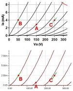
For example, suppose a 12AT7 half-mu is biased at point A on the upper diagram. Both valves are biased at this point, so ra is equal in the two devices. Now when amplifying a signal, one valve moves to point B while the other must move to point C. They both see the same current, but the voltage across one has fallen while the other has risen. You can see from the green lines that the anode resistances of the two valves are now quite different, i.e. they don't cancel out.

In the lower image we see the SPICE model of the same tube. Here points B and C show the same anode resistance, so they would cancel out and give ideal linearity. SPICE has fooled us with its naive model.
Attachments
Last edited:
That could be quite helpful. It might put a stop to some of the newbies posting circuits and claiming excellent distortion figures which are pure fiction, derived as they are from simulation alone.DualTriode said:Perhaps we need some Monty Carlo randomness when we simulate two triodes in a circuit to avoid having perfect triode matching and perfect distortion cancellation. (Just a little tongue in cheek).
As I don't use simulation very much, and would largely ignore distortion figures if I did, I did not realise that SPICE valve models were so poor. Sufficiently poor, in fact, to be almost useless for circuit design apart from a first wild stab at bias point. Surely all the models are not as bad as the 12AT7 one you show?Merlinb said:The problem is that SPICE models, and the simple theory, assume the internal anode resistance does not vary with voltage, only with current.
Spice simulation is as good as the person who uses it. You can always change the circuit topology such as mu or srpp topology, split-ted into top and bottom tubes instead of cascading or stacking thereby avoided such pitch-fall. This problem is well known so it is strictly not a Spice problem, spice won't know how to deal with all the look-alike circuits created by human.
Last edited:
Hi ! ,Hello Dimitris,
You were asking directly. Here is the direct answer.
Yes that top triode is an active device. If there is a spectrum that falls between full on active current controlling device and completely passive pure resistance that top triode falls much closer to the passive resistance end of the spectrum.
See post number 68, I replaced the top triode with a resistor, as far as I could tell with the Audio Analyzer FFT there was no difference between the circuit with the triode in place verses the resistor. The results were the same.
The greybeards called that top triode as being equivalent to a resistor. I do not want to change it now.
DT
I know well how active devices behave , simply I thought that you are confusing things a little bit , but now I read your post ( # 68 ) and I understand what you want to say ! . IMO the triode act as an active device in the half mu circuit too , but the reason that you get the same distortion spectrum ( with the triode and with the resistor ) is because the output in the half mu circuit is taken from the anode of the lower triode , therfore the current of the top triode ( to the load ) pass thru its Rk resistor ! , I believe that this function plays a " major " role in the final result .
Last edited:
Hello Dimitris,
Okay!
Assuming that the Half-Mu has little or no load (the load is the grid of the next stage) a grounded cathode amplifier with a plate resistor having a voltage drop equal to the voltage drop across the top triode and cathode resistor of a Half-Mu amplifier performs much the same as the Half-Mu amplifier.
The gain is the same. The output impedance is the same. The distortion spectrum is the same. Did I miss anything? That is the same too.
With all the performance parameters the same what major role does the top triode of the Half-Mu Play?
The top triode can play a major role when there is a significant external load or if that load is attached at the cathode of the top triode. However we are not speaking of a Half-Mu circuit any longer.
The Half-Mu does have some listed advantages;
Compensating for a different B+ voltage.
Compensating for a different heater voltage.
Compensate for tube age.
A resistor does not do this compensation.
DT
The major role is that , the half mu will compensate for a different B+ voltage , because you will have 1/2 of B+ voltage each time on the output, compared to the grounded cathode amplifier , which you have to change the anode and the cathode resistor , each time you change the B+ voltage, to achive 1/2 of B+ voltage on its output. On the other hand SRPP (output from the cathode of top triode) have better distortion spectrum and lower output impedance and can deal easier with higher loads! and lower Rk leads to lower output impedance of course!
Hi,
On the other hand SRPP ( output from the cathode of top triode ) have better distortion spectrum and lower output impedance and can deal easier with higher loads ! and lower Rk leads to lower output impedance of course ! .
Further to that it has been shown that SRPP performs best with a high, fixed load that is optimized for lowest distortion.
Horses for courses as usual.
Many decades ago we compared performances of several topologies in phono preamps using passive RIA correction.
The conclusion was that the power supply topology used had far more impact on the end results then the actual topology of the circuit's topology proper.
Cheers,
- Home
- Amplifiers
- Tubes / Valves
- Survey: Aikido distortion